Nintendo Virtual Boy
Nintendo's tabletop stereoscopic 3D console (1995), a red monochrome display via LED scanning. A commercial failure, but a cult one. THE emblematic fault: the display ribbons that come unstuck → missing lines/columns. A well-known repair.
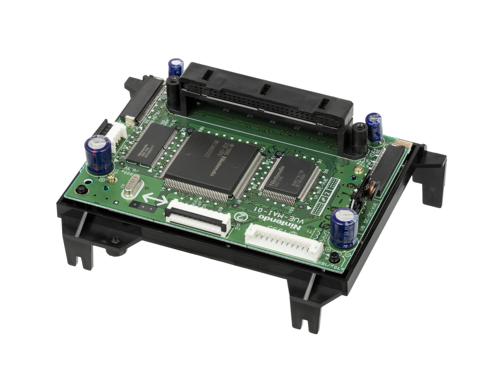
Identification
| Field | Value |
|---|---|
| Manufacturer | Nintendo |
| Release | 1995 |
| Type | Tabletop 3D console (visor) |
| Display | monochrome red LED, scanning (mirror scan) |
| CPU | NEC V810 (32-bit) @ 20 MHz |
| Resolution | 384×224, 4 levels of red |
| Principle | 2 linear LED arrays (1×224) + an oscillating mirror per eye → image scanning (stereoscopy) |
⚠️ The cult fault: the display ribbons
Missing lines/columns = an unstuck ribbon
The flex ribbons connecting the controller to the LED arrays are glued (conductive adhesive) that degrades → missing lines or columns appear, then a dead display. It's the Virtual Boy defect.
Repair: remove the old glue and re-solder the ribbon (heat re-flow, or a permanent soldered fix). A delicate but documented operation.
Why the scanning?
Each eye has only a vertical array of 224 red LEDs; an oscillating mirror driven by a motor sweeps sideways to form the 384 image columns. This mechanical system (plus the single red colour, cheaper and lower-power) explains both the stereoscopic 3D and the fragility.
Power & ergonomics
Powered by 6 AA batteries (via a "Tap" under the controller) or an optional AC adapter. The console sits on an adjustable stand; a hardware auto-pause prompts breaks (Nintendo's "health" precaution). The announced link cable was never released.
Common faults
| Symptom | Likely cause | Lead |
|---|---|---|
| Missing lines / columns | Unstuck display ribbon | Re-flow / re-solder the ribbon |
| Only one eye displays | Ribbon / LED array on one side | Same, on the affected side |
| Nothing on screen | Power, contacts, ribbons | Diagnosis |
Step-by-step disassembly procedures ✅
1 procedures transcribed from the iFixit guides, with difficulty and estimated time.
| Procedure | Difficulty | Time |
|---|---|---|
| Nintendo Virtual Boy Teardown | Moderate | No estimate |
Nintendo Virtual Boy Teardown
Our week of game console teardowns is coming to a close, and we have a super-extra-special teardown for today. We partnered with Engadget to bring you a glimpse of one of the most interesting game consoles ever. Direct quote from the guys who created the teardown: "The Virtual Boy is bar none the coolest device we've ever taken apart." Everyone at the office agrees that it's an awesome console, so much so that there have been arguments over who's going to play it next. Nintendo called the Virtual Boy a "32-bit, 3-D experience" that "eliminates all external stimuli, totally immersing players into their own private universe." Even so, TIME Magazine listed the Virtual Boy as one of the worst inventions of all time, and PC World called it one of "the ugliest products in tech history." Of course, neither Time nor PC World ever opened one, so what do they know? Join us today as we delve into the mystery behind the Virtual Boy's controversial and short-lived existence.
- The Virtual Boy was only available in North America for seven months -- from August 14, 1995 until March 2, 1996 -- with only 770,000 units sold. Compare that with the Nintendo 64, which sold 32.93 million units over its lifespan.
- Tech Specs:
- 20 MHz, 32-bit RISC Processor
- 128 KB dual-port VRAM
- 384 x 224 pixel resolution
- 2-bit monochrome display (black and three shades of red)
- 16-bit stereo sound
- The Virtual Boy probably doesn't deserve to be ranked as one of the ugliest pieces of machinery of all time, but it does bear a striking resemblance to certain sci-fi characters.
- The Neoprene eyepiece completely encompassed the player's field of vision. This not only isolated the player from the rest of the world, but prevented anyone else from seeing what the player was doing.
- If only the Virtual Boy could play "other" content...
- Games such as Mario's Tennis support the use of the Extension port on the underside of the Virtual Boy. Regrettably, Nintendo never got around to releasing an appropriate cable.
- There were only 22 games made for the Virtual Boy, and only 14 of those were released in North America. Top hits include: Mario's Tennis, Wario Land, 3D Tetris, and Teleroboxer.
- In order to deliver a full range of motion in a virtual 3-D environment, a method of controlling motion in the z-axis was required. To overcome this hurdle, a second D-pad was added to the controller.
- No, that is not an infared image of Wario. The Virtual Boy took full advantage of the three shades of red available to create on-screen images.
- It took a while to snap that screenshot because Wario kept fidgeting.
- Unfortunately, taking the Virtual Boy apart is not a walk in the park.
- When we found out that our 1/4" drive gamebit did not fit down into some of the recessed screw holes, we had to get creative.
- After donning safety glasses and throwing many sparks from our rotary cutoff wheel, we ended up with a nice little gamebit socket that is easy to turn with a flathead screwdriver.
- With that out of the way, we can finally start taking this thing apart.
- The neoprene eye shield and its frame pop right off the rear of the Virtual Boy.
- After making short work of the screws securing the tripod base with our custom gamebit, it can be lifted off the lower case.
- Nintendo apparently had repair in mind when they designed the tripod base, as it is easily removable in the [likely] event that the tripod base would break during a fall.
- After removing the rest of the hard-to-access screws, you can lift off the lower case from the Virtual Boy.
- Several ribbon cables attach the main board to the main components across the Virtual Boy. After disconnecting them, the board easily comes out.
- The main board is responsible for taking inputs from the controller, loading game cartridge data, sending audio data to the speaker amplifier, and driving the LED displays. The silk screened chips include:
- Nintendo '95 VUE-VPU, 9520KK023
- Nintendo NVC-VUE, (C) NEC '91 '93 9520KX003
- Nintendo VRM-VUE, 9508KU028
- Toshiba TC511664BJ-80 128 KB of DRAM
- Toshiba TC511632FL-70
- Nintendo '95 VSU-VUE ATT, 9507A3014
- Texas Instruments 57A5CXK, HCU04
- A couple Phillips screws secure the controller port and sound boards to the upper case.
- After removing the screws, both boards can be lifted out of the Virtual Boy.
- The modular construction of the Virtual Boy indicates it was designed with repair in mind. A damaged controller port or audio system could be individually replaced rather than replacing a single all-encompassing motherboard if one of its components failed.
- The controller board and the sound system come out, followed by the display assembly.
- As you'll soon find out, the rubber isolators between the metal display assembly chassis and the upper case are designed to dampen vibrations originating from the Virtual Boy's two oscillating mirrors.
- When the knob on the top of the Virtual Boy is rotated to adjust the inter-pupil distance (the center-to-center distance between pupils), the two display units move closer or further away from each other.
- When the focus slider is slid back and forth, the lens in each display unit moves relative to the stationary LED display.
- The Virtual Boy's 3D capabilities are a result of an effect known as parallax, in which a single image is viewed along different lines of sight.
- This process is the basis for the method by which the human eye is capable of perceiving depth. Each eye receives a slightly different image (being a few inches apart and along different sightlines). The brain then interprets these two images into a single 3D image. This effect is called stereopsis.
- The Virtual Boy uses each display to send a slightly different image to each eye, thereby creating a stereoscopic 3D image.
- The Virtual Boy employs an extremely creative way of producing its unique binocular (and 3D) graphics.
- A one-pixel-tall row of LEDs at the far end of each display unit projects light through a lens in the middle of each unit.
- After passing through the lens, light is reflected off a mirror situated at 45° that oscillates about its central axis.
- The mirror oscillates and the LED refreshes with such speed that the human eye perceives a single image across the view plane.
- To oscillate the mirror, alternating electrical current at high frequency is passed through a copper coil attached to the mirror. A stationary iron core is attached to the display unit, forming a solenoid to produce the motive force needed for oscillation.
- To tell the oscillator circuitry how fast the mirror is moving, an arm attached to the mirror passes back and forth through an optical sensor attached to the lower circuit board.
- The board you see here is responsible for driving the oscillation of both mirrors.
- The chips on this board receive display information from the main board and ensure that the mirrors are oscillating at the correct frequency by receiving feedback signals from the optical sensors shown in the previous step.
- An 8 MHz crystal soldered to the board is used for timing the oscillation of the mirrors.
- Two T10 Torx screws secure the LED unit to the end of the display assembly.
- After the LED unit is removed, you can see the "periscope" style reflection and slight magnification caused by the 45° mirror and the internal lens.
- The Virtual Boy display! Each 4-color display unit was manufactured by Reflection Technology Inc., and featured a 1x224 pixel resolution with 32 levels of intensity.
- Each "image" produced by the display is merely a row of red dots. Used in conjunction with an oscillating mirror, a full image is produced.
- Because the entire image is produced by a single row of LEDs, the refresh rate is incredibly high. Each pattern of LEDs is displayed for only 0.000052 seconds!
- LCDs were considered as an option for the display, however they could not refresh fast enough and caused blurry images. LEDs became the option of choice as they could refresh fast enough and were bright enough to create a steady, bright image.
- The developers looked into using multiple colors in the display, but they were limited by price. Red LED's were chosen because they were the cheapest, most efficient, and most visible LEDs.
- What a spectacular end to a week of retro: Magnavox Odyssey 100, RCA Studio II, Atari 2600, Famicom, and now the Virtual Boy. We hope you had fun -- we sure did!
- Public Announcement: We have a brand new game console parts store to help keep your (slightly more modern) consoles at their most optimal performance!
Source, licence and scope
iFixit guides, under Creative Commons BY-NC-SA — attribution, non-commercial, share-alike. Only the text is reproduced; the step photos stay on iFixit. ⚠️ These guides target the model named in the title: on another revision, the screws and the order of removal may differ.
Procedure — a dead console, step by step ✅
What this adds
Ordered for a console, not for an arcade board: what kills these is almost never the CPU. It is, in real order, the power supply, the capacitors, the drive or the cartridge slot, and only then the logic. → PCB diagnosis
1. The power supply. Two cases, depending on the machine. External brick: ⚠️ read the marking on the machine, next to the socket, and check the adapter against it — voltage and polarity. A centre-negative machine fed centre-positive loses its fuse, sometimes its regulator; do not trust a third-party label or a generic tip. Internal supply (the machine plugs straight into the wall): mains is inside the shell. Unplug, wait, and confirm the large capacitors are discharged before touching the board. Either way, measure under load: a failing supply holds its voltage until it is asked for current.
1b. Battery and its contacts. On this machine, before anything else: corroded battery contacts, or a cell that reads fine off-load and collapses under it, give exactly the symptoms of a dead machine.
2. The fuse. Many of these machines have one right behind the socket — it is the part designed to die. Test it in continuity, out of circuit. A fuse that blows again is a short, not a fuse problem.
3. Capacitors. On most machines of this age this is the default suspect rather than a last resort — leaking SMD electrolytics eat the tracks underneath before they give any other sign. ⚠️ Not all of them are like that: some carry very few and are not recapped on principle. Read what this page says about it before reaching for the iron. → Recap
4. The cartridge connector. Cartridge contacts with isopropyl alcohol, never an abrasive eraser: it takes the gold plating off and the problem comes back worse. On the machine side, inspect the slot pins — splayed, bent or oxidised — and check continuity between slot and board.
5. The screen. Lines, a dead half, a picture that fades: it is almost always the ribbon and its solder joints, not the panel. Reseat before you order anything. If this machine has a TV output — not all of them do — test that too: it tells the screen apart from what feeds it.
6. Still nothing. Now, and only now, the logic: rails on the board, reset, clock, bus. → PCB diagnosis
Library & preservation
- Only ~22 games (14 JP, 14 US, partial overlap): Mario's Tennis (US pack-in), Galactic Pinball, Red Alarm, Teleroboxer, Virtual Boy Wario Land (the most acclaimed), Jack Bros.… The promised catalogue (including a Zelda) was cancelled.
- Flashcart: FlashBoy / FlashBoy Plus (RetroOnyx) — homebrew + library. An active homebrew scene despite everything.
- Emulation: Mednafen (VB core), with anaglyph/2-colour rendering or VR headsets.
Mods & repair — what to buy, how
Display ribbon fix — THE VB repair
- Symptom: missing or flickering rows/columns on one of the two displays. Cause: the display's ribbon flex is bonded with a conductive resin that degrades over time.
- Permanent fix 🟠: instead of reheating/re-gluing (temporary), you re-solder the flex to the display-driver board (desolder the ribbon, clean, resolder with iron/hot air). Kits offer a replacement flex/board. It's the emblematic VB mod/repair.
Library & misc
- Flashcart: FlashBoy / FlashBoy Plus (RetroOnyx) — games/homebrew on cartridge, plug-and-play 🟢.
- AV / video output: community mods to capture/display the red mono image on an external screen.
- Power: the VB runs on 6 AA cells (or the mains adapter) → modern power mods are common.
Photos / assets
(To add: interior, display ribbons, LED arrays.)
Advanced repair
Glitching/disappearing display ribbon = THE emblematic fault → reflow the heat-bonded ribbons (conductive glue). Methods: Traces & vias · PCB fault-finding · Recap.
Sources & attribution
- Wikipedia — Virtual Boy — CC-BY-SA — https://en.wikipedia.org/wiki/Virtual_Boy
- ConsoleMods / VB community — ribbon repair — to reference
Image:
-
virtual-boy-board.jpg— Evan-Amos, public domain — https://commons.wikimedia.org/wiki/File:Nintendo-Virtual-Boy-Motherboard-BR.jpg

Review & corrections
How this space is used
Spotted a wrong value, an outdated procedure, a chip reference that does not match your board? Say so here, with what you observed (model, board revision, serial number, measurement). Every report is cross-checked against a source before anything changes — an unverifiable correction is published as “reported by …, not cross-checked” rather than silently applied.
Reading is open to everyone; posting requires signing in with Discord. Reports from the wiki's declared reviewers are handled first; anyone else's are read too, but go through a human before anything is changed.