Sony PlayStation (PS1)
Console 32 bits de Sony (1994), à CD-ROM, qui a fait basculer le jeu vidéo vers le grand public. RGB natif superbe. Points préservation : le lecteur CD (laser qui s'use, le classique « console à l'envers ») et les ODE modernes (PSIO, xStation).
Identification
| Champ | Valeur |
|---|---|
| Fabricant | Sony |
| Sortie | 1994 (JP), 1995 (export) |
| Génération | 5e (32 bits) |
| Révisions | SCPH-1000 → 9000 · PSone (SCPH-100) |
| Sortie vidéo native | Composite, S-Video, RGB |
| Région / lockout | JP / US / EU |
| Média | CD-ROM |
Architecture
| Bloc | Puce | Fréquence | Rôle |
|---|---|---|---|
| CPU | MIPS R3000A (LSI CoreWare) | ~33,87 MHz | + GTE (Geometry Transform Engine, coproc. 3D) + MDEC (décodeur vidéo) |
| GPU | custom Sony | rastériseur 2D/3D, pas de correction de perspective (d'où les textures « qui ondulent ») ni de Z-buffer | |
| Son | SPU | 24 voies ADPCM + réverbération | |
| Mémoire | 2 Mo principale + 1 Mo VRAM + 512 Ko son | ||
| Média | CD-ROM 2× | + carte mémoire (sauvegardes) |
La 3D en nombres entiers (pas de virgule flottante par pixel) explique le tremblement des polygones (« vertex jitter »), signature visuelle de la PS1. L'absence de correction de perspective fait « onduler » les textures — deux défauts que l'émulation moderne (PGXP) sait corriger.
Manettes & périphériques
- Évolution du pad : digital d'origine → Dual Analog (SCPH-1150) → DualShock (2 sticks analogiques + vibration), qui devient le standard.
- Multitap (SCPH-1070) : 4 à 8 joueurs.
- GunCon / G-Con (Namco, light gun CRT), neGcon (manette qui se tord, Ridge Racer), Jogcon (R4), volant, souris.
- PocketStation (Japon) : carte mémoire avec écran LCD = mini-console (interagit avec certains jeux).
- Carte mémoire 128 Ko (15 blocs) ; alternative moderne MemCard PRO.
- Link cable (SIO) : relier 2 consoles + 2 TV (Wipeout, Doom).
Révisions de carte (PU-7 → PU-23)
La PS1 « fat » a de nombreuses révisions de carte mère (repère PU-xx), au fil d'une réduction de coûts continue :
| Carte | Modèles (SCPH) | À retenir |
|---|---|---|
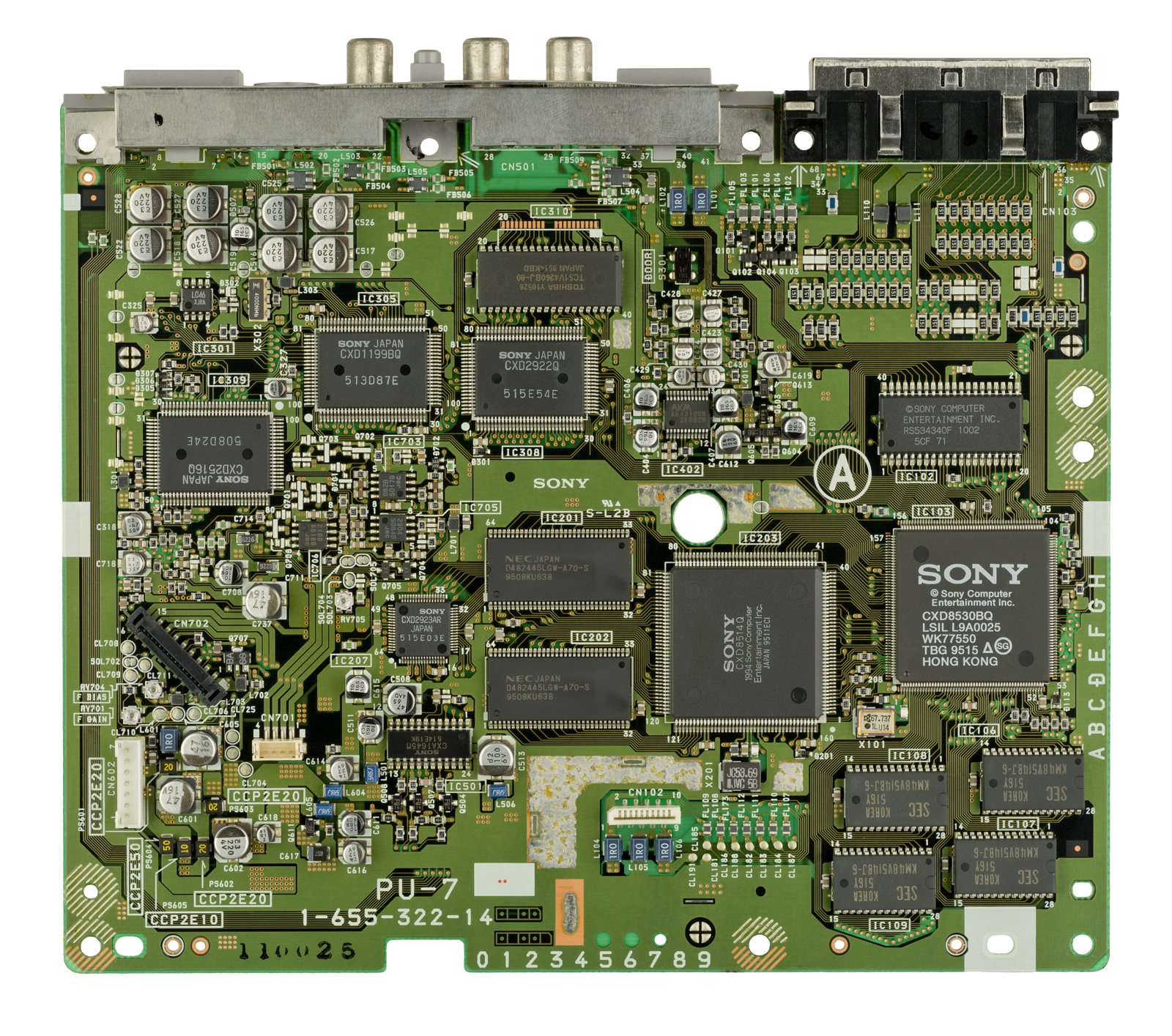
| PU-7 | SCPH-1000 (+ 1002 EU) | lancement ; sortie audio RCA dédiée + S-Video, ports parallèle & série ; DAC audio réputé (recherché) |
| PU-8 | SCPH-100x / 300x / 500x | cost-reduction ; AV multi-out |
| PU-18 | SCPH-5500 → 5503 | révision très répandue |
| PU-20 | SCPH-5903 (Video CD) & co. | variante |
| PU-22 | SCPH-7500 | port parallèle retiré |
| PU-23 | SCPH-9000 | dernière « fat » ; port série retiré sur les tardives |
| PM-41 | PSone (SCPH-100) | redesign compact 2000 |
Mappings SCPH-5500-5503 = PU-18, SCPH-7500 = PU-22, SCPH-9000 = PU-23 confirmés par les schémas Console5. Les cartes early (PU-7/8) sont prisées pour leur A/V et leurs ports d'extension ; les tardives sont plus fiables mécaniquement mais dépouillées. La PSone (PM-41) est compacte, sans port parallèle/série, alimentée par un bloc externe.
Le bloc laser (KSM-440) & le « à l'envers »
Le lecteur utilise un bloc optique de la famille KSM-440 (variantes KSM-440AAM/ADM/BAM selon révision). Deux usures classiques :
- Laser affaibli : la diode perd en puissance → sauts, refus de lecture. Un potentiomètre sur le bloc règle le courant laser (dernier recours seulement).
- Rail / engrenage plastique : le chariot force → lecture aléatoire.
Pourquoi la console « lit à l'envers »
L'astuce bien connue (retourner/incliner la console pour lire) marche parce que changer l'orientation compense un laser faible / un rail usé (gravité sur le chariot ou la lentille). C'est un symptôme d'usure : la vraie réparation est le réglage/remplacement du laser — ou un ODE qui supprime le lecteur.
Recap (secondaire)
Contrairement au Duo NEC ou à la Game Gear, la PS1 n'est pas une console « à recap » critique. Un recap n'aide qu'en cas de son/vidéo dégradés ou d'alim capricieuse. Les listes par repère existent par révision PU (et par module d'alim 100-120 V / 220-240 V) chez Console5 — voir sources.
Pannes fréquentes
| Symptôme | Cause probable | Piste |
|---|---|---|
| Ne lit plus / ne lit qu'à l'envers | Laser / rail / gears usés | Régler le laser, remplacer le bloc optique, ou ODE |
| Sauts de lecture | Laser faible | Régler le potard laser ; ODE |
| Pas d'image | Alim, GPU, contacts | Diagnostic |
| Pile carte mémoire | (sauvegardes sur carte externe) | Remplacer la carte |
Manuel de service d'origine ✅
Manuel constructeur archivé localement. Contient typiquement les schémas, le synoptique, les tensions et formes d'onde attendues, la nomenclature et les procédures de dépose — c'est la référence quand un symptôme ne colle à aucune panne connue.
Statut
Document constructeur sans licence explicite, conservé à titre de préservation (machine hors production depuis des décennies) — même position que pour les manuels de bornes et d'arcade déjà archivés ici. Source : Internet Archive.
Procédures de démontage pas-à-pas ✅
18 procédures traduites depuis les guides iFixit, avec leur difficulté et leur durée estimée. Le titre d'origine est rappelé sous chaque procédure, pour retrouver le guide et ses photos.
| Procédure | Difficulté | Durée |
|---|---|---|
| Démontage complet | 🟡 moyen | non estimée |
| Ouverture du boîtier (préalable) | — | — |
| Ouverture du boîtier (variante) | — | — |
| Démontage du boîtier | — | — |
| Réglage de vitesse du moteur (SCPH-5501, KSM-440ADM/AEM+) | 🟠 difficile | 1 à 3 heures |
| Démontage complet d'une SCPH-9002 | 🟡 moyen | non estimée |
| Démontage complet — 25 ans de la PlayStation | 🟡 moyen | non estimée |
| Remplacement du bloc des ports manette (variante) | — | — |
| Remplacement des ports manette | 🟡 moyen | 10 à 20 minutes |
| Remplacement du bloc optique (SCPH-1001) | 🟡 moyen | non estimée |
| Remplacement du laser par celui d'une SCPH-7501 ou SCPH-9001 | — | — |
| Dépose de la carte mère (variante) | — | — |
| Remplacement de la carte mère | 🟡 moyen | 20 à 30 minutes |
| Remplacement du bloc optique | 🟡 moyen | 10 à 20 minutes |
| Dépose du bloc optique (variante) | — | — |
| Remplacement du bloc optique par celui d'une SCPH-7501 ou SCPH-9001 | — | — |
| Remplacement de l'alimentation | 🟡 moyen | 10 à 15 minutes |
| Dépose de l'alimentation (variante) | — | — |
Démontage complet
- Retourne la console pour accéder aux six vis du dessous.
- Retire les six vis indiquées au tournevis cruciforme. Elles sont toutes de la même longueur.
- Remets la console à l'endroit et dégage la moitié supérieure vers le haut.
- Débranche de la carte mère le câble d'alimentation et la nappe du bloc laser.
- Retire les deux vis du bloc carte mémoire / ports manette, débranche la nappe et sors-le du boîtier.
- Pour déposer l'alimentation : débranche son câble, retire les deux vis, puis sors-la du boîtier.
- Retire les 3 vis du blindage.
- Retire les 5 vis cruciformes.
- La carte mère peut maintenant être sortie du boîtier.
- Sors le blindage RF du boîtier.
- Au remontage, repose le blindage RF en alignant les fentes et les ergots.
- Repose la carte mère. Ne remets que les vis repérées en rouge.
- Repose le blindage supérieur et ses 3 vis.
- Repose le bloc carte mémoire / ports manette : rebranche la nappe et remets les 2 vis.
- Aligne le bloc optique sur ses trois picots.
- Rebranche les câbles d'alimentation et de données du bloc optique.
- Fais glisser le capot comme tu l'as retiré et remets les vis noires.
- Rebranche la console et allume-la.
Titre d'origine : « (TC) PlayStation Teardown ».
Ouverture du boîtier (préalable)
Procédure d'ouverture, préalable aux autres interventions.
- Avant de commencer, vérifie que la console est éteinte et débranchée. Retourne-la et retire les cinq vis cruciformes n° 1 de 15,8 mm.
- En maintenant les deux moitiés ensemble, remets la console à l'endroit. Soulève le capot supérieur à la verticale.
Ouverture du boîtier (variante)
Même procédure, rédigée par un autre contributeur.
- Retourne la console et retire les cinq vis cruciformes n° 1 de 15,8 mm.
- Remets-la à l'endroit en maintenant les deux moitiés ensemble, puis soulève le capot supérieur.
Démontage du boîtier
Ouverture du boîtier en passant par le cache du port parallèle.
- Retire le cache du port parallèle, à l'arrière de la console.
- Retourne la console et retire les six vis du dessous.
- Remets-la à l'endroit et soulève le capot.
Réglage de vitesse du moteur (SCPH-5501, KSM-440ADM/AEM+)
Ta SCPH-550x lit mal les jeux ? Cette procédure prolonge la vie du laser existant plutôt que de le remplacer. ⚠️ Elle ne s'applique qu'aux blocs à châssis moulé — les blocs plastique ne sont pas réparables.
- Avant de commencer, vérifie que tu as un laser à châssis moulé. Un laser plastique n'est pas réparable.
- Si ton laser est en plastique : il faut le remplacer, son usure est irrégulière.
- Avec un laser à châssis moulé, ce réglage peut améliorer le taux de lecture. Mais la panne est liée à l'âge, et la résistance du laser doit parfois être ajustée en plus.
- Retire les 6 vis sous la console, au tournevis cruciforme n° 2.
- Soulève le capot supérieur.
- Débranche le bloc laser de la console.
- Le bloc déposé, retire les 2 vis cruciformes PH1. Vérifie à ce moment si le laser est en plastique.
- S'il est en plastique, il ne peut pas être réparé et doit être remplacé.
- Ne règle que ce qu'il faut pour relire jeux et CD audio de façon fiable. Une vitesse trop lente peut, en théorie, marquer les disques.
- Considère un taux de lecture inférieur à 80-90 % comme un échec : ces cas se récupèrent mal.
- Avant de toucher au réglage, repère la position d'origine et note le réglage d'usine tel que tu l'as mesuré. Sans cette information, revenir en arrière est très difficile.
- Tourne le potentiomètre par petits pas, avec un embout PH1 ou compatible, jusqu'à ce que la lecture devienne plus régulière.
- Si possible, teste d'abord sur une console dont tu sais qu'elle fonctionne.
- Pour améliorer le taux de lecture : si le résultat ne te convient pas, continue à ajuster. Répète jusqu'à obtenir un taux satisfaisant, ou jusqu'à ce que le moteur ne tourne plus.
- Si l'écran « Insert PlayStation CD-ROM » apparaît, le moteur tourne trop lentement : accélère.
- Remonte partiellement et teste. Si le résultat convient, termine le remontage.
- Pour mesurer le taux de lecture, essaie plusieurs jeux dont tu sais qu'ils sont en bon état. Cinq jeux minimum, et ne retouche le réglage qu'après une série complète.
- Si le jeu se lance, joue quelques minutes pour vérifier la stabilité. Certaines révisions anciennes ont des défauts sur les séquences vidéo : c'est normal.
Titre d'origine : « PlayStation SCPH-5501 Motor Speed Adjustment (KSM-440ADM/AEM+) ».
Démontage complet d'une SCPH-9002
Démontage d'une PlayStation SCPH-9002.
- La console avant démontage.
- Retourne-la et retire les six vis.
- Référence de vis : +BV 3×14.
- Retire le capot supérieur : il vient sans difficulté.
- Débranche les deux connecteurs du lecteur CD.
- Premier connecteur CD et son embase.
- Second connecteur CD et son embase.
- Référence du bloc optique : KSM-440AEM.
- Retire le lecteur CD. Il se tire doucement, en le faisant jouer un peu pour libérer les silentblocs en caoutchouc.
- Débranche les deux câbles : l'un va à l'alimentation, l'autre aux cartes mémoire et ports manette.
- Retire les quatre vis et le capot métallique.
- La carte mère est accessible.
- Et l'alimentation aussi.
- Retire les quatre vis de la carte mère et de l'alimentation.
- Une fois les vis retirées, dépose l'alimentation.
- Dépose la carte mère, puis les deux vis du bloc carte mémoire / ports manette.
- Tous les éléments sont maintenant séparés :
- Carte mère.
- Coque inférieure.
- Blindage anti-interférences.
- Alimentation.
- Bloc optique.
- Bloc carte mémoire / ports manette.
Titre d'origine : « Sony PlayStation SCPH-9002 Teardown ».
Démontage complet — 25 ans de la PlayStation
Née d'un projet commun Sony-Nintendo de Super Nintendo à CD-ROM, la PlayStation est devenue l'une des consoles les plus vendues de l'histoire. Démontage anniversaire d'une SCPH-1000.
- La PlayStation n'a été vendue qu'au Japon pendant sa première année. Ce qu'on attendait :
- Processeur MIPS R3000 32 bits RISC à 33,9 MHz.
- Processeur graphique 32 bits.
- 2 Mo de RAM.
- 1 Mo de VRAM.
- Son PCM stéréo 16 bits sur 24 voies.
- Lecteur CD-ROM 2×.
- La console est souvent appelée « PSX » : c'était son nom de code en développement, et il est resté après l'abandon officiel du X.
- De loin, le modèle japonais est identique au modèle nord-américain. De près, quelques différences apparaissent.
- L'intérieur des tiroirs CD est presque identique, à quelques détails de moulage près.
- La différence la plus visible est le logo sur le capot : le modèle japonais tire sur le vert, avec un brun dans les réserves du logo, là où l'occidental est en bleu PlayStation.
- Ces couleurs rares n'apportent évidemment aucun gain de performance.
- L'arrière révèle une connectique abondante — sans commune mesure avec un portable moderne.
- Les étiquettes japonaises décrivent chacun des ports.
- Sur le modèle occidental, elles sont en anglais. Détail des sorties :
- Parallel I/O : Sony n'a jamais sorti de produit officiel exploitant ce port, mais beaucoup de dispositifs de triche tiers s'y branchaient.
- Serial I/O : relie deux PlayStation pour jouer à plusieurs sur deux téléviseurs — seuls certains jeux le géraient.
- RCA Out : sortie non propriétaire vers le téléviseur.
- RFU DC Out : alimente un modulateur RF, pour les téléviseurs sans entrée RCA.
- S-Video Out : présent uniquement sur la SCPH-1000 japonaise. Selon le téléviseur, beaucoup le jugent supérieur aux autres sorties.
- AV Multi Out : le connecteur propriétaire Sony pour l'image et le son. Les câbles RCA, S-Video et RF pour ce port ont fini par remplacer toutes les autres sorties.
- AC In : câble et connecteur C7/C8 standard, en version polarisée sur le modèle nord-américain. Sony a conservé ce connecteur sur toutes ses PlayStation depuis.
- Face à la PlayStation Classic, la console d'origine paraît immense.
- La Classic reprend honorablement les détails du modèle d'origine — jusqu'aux ouïes latérales et aux emplacements de carte mémoire.
- Une omission reste difficile à pardonner : le capot CD ne s'ouvre pas, alors qu'un vrai bouton Open invite à essayer.
- Revenons au démontage.
- Comment entrer ? Ces flèches donnent un indice.
- Chaque vis qui tient les deux moitiés est repérée par une petite flèche.
- Après une année d'appareils collés et difficiles à ouvrir, l'attention fait plaisir.
- Un seul embout suffira pour tout le démontage.
- On soulève le capot de cette console.
- Pas de trésor caché, mais du beau matériel.
- Commençons par écarter l'alimentation avant de prendre une décharge.
- Cette alimentation interne occupe environ 20 % de l'emprise au sol de la console.
- Le silicium des années 90 chauffait moins qu'aujourd'hui, mais loger une alimentation interne, un bloc optique et toute la carte mère sans ventilateur reste remarquable.
- Les ports manette et les lecteurs de carte mémoire sortent d'un seul bloc.
- Les cartes mémoire de 1 Mo étaient découpées en 15 blocs, ce qui permettait de sauvegarder plusieurs jeux sur une seule carte.
- Le bloc laser et son moteur reposent sur trois picots à silentblocs en caoutchouc : l'ensemble peut bouger légèrement pour absorber les vibrations du disque.
- Certains estiment que les premiers modèles à prises RCA offraient une excellente restitution en lecture de CD audio — le débat dure depuis la sortie de la console.
- Ne touche jamais la lentille.
- On soulève le grand blindage métallique qui cache la carte mère.
- La carte se dépose avec précaution.
- Elle est couverte de circuits :
- Sony CXD8530BQ — processeur (conception MIPS).
- Sony CXD8514Q — processeur graphique (conception Toshiba).
- Samsung KM48V514BJ-6 — DRAM (4 × 512 Ko).
- Sony M534032C-02 — ROM.
- Samsung KM4216V256G-60 — VRAM (2 × 512 Ko).
- Sony CXD2922Q — processeur sonore.
- Sony CXD1199BQ — décodeur CD.
- Et quelques autres :
- Sony CXD2516Q — processeur de signal numérique du CD.
- Samsung KM416V256ALLT-8 — RAM audio.
- Sony CXD2923AR — convertisseur numérique-analogique.
- Sony CXA1645M — encodeur vidéo.
- Au dos de la carte, d'autres circuits encore :
- Sony E35D 424660 185 BRSAC9505A — contrôleur CD.
- Hitachi HM62W256LFP-7T — SRAM CMOS.
- Rohm BA6398FP — étage de puissance 4 voies en pont.
- Sony A1782BR — amplificateur d'asservissement et traitement du signal RF.
- Toshiba TA78M05F — régulateur d'alimentation.
- Vingt-cinq ans séparent cette carte d'une PlayStation 4, qui a près de 50 fois la puissance de calcul et 4 000 fois plus de mémoire.
- Il n'y a pas grand-chose à l'intérieur, ce qui en dit long sur la conception — et sur la simplicité relative de l'époque.
- Sony a réussi l'essentiel dès sa première console.
- Cela, plus un catalogue de jeux remarquable, a porté la PlayStation plusieurs fois en tête des consoles les plus vendues. Le modèle d'origine occupe aujourd'hui la 5ᵉ place de ce classement.
- Fin de ce démontage anniversaire. Reste à donner une note de réparabilité.
- La Sony PlayStation (SCPH-1000) obtient 8 sur 10 en réparabilité (10 = le plus facile à réparer) :
- La console compte peu de composants, et chacun se dépose et se remplace simplement.
- Un tournevis cruciforme et un spudger suffisent au démontage complet.
- Le bloc optique est l'un des éléments les plus faciles à retirer — appréciable, vu sa propension à lâcher sur les premiers modèles.
- La documentation de réparation est largement disponible.
- Tous les connecteurs de la face arrière sont soudés à la carte mère.
Titre d'origine : « Sony PlayStation Teardown ».
Remplacement du bloc des ports manette (variante)
Dépose du bloc des ports manette, une fois le boîtier ouvert.
- Retire les deux vis qui fixent le bloc des ports manette au boîtier.
- Débranche doucement la nappe de la carte mère, en tirant sur la partie bleue du câble près du connecteur.
- Dépose le bloc et remplace-le.
Remplacement des ports manette
Si la console ne détecte plus les manettes ni les cartes mémoire, il est peut-être temps de remplacer le bloc des ports.
- Avant de commencer, vérifie que la console est éteinte et débranchée.
- Retourne la console et retire les cinq vis cruciformes n° 1 de 15,8 mm.
- En maintenant les deux moitiés ensemble, remets la console à l'endroit. Soulève le capot supérieur à la verticale.
- Retire les cinq vis cruciformes n° 1 du blindage métallique des ports manette :
- Deux vis de 14 mm.
- Trois vis de 8 mm.
- Soulève le blindage à la verticale.
- Débranche la nappe des ports manette en la tirant droit hors de son connecteur sur la carte mère.
- Soulève le bloc des ports manette hors de la coque inférieure.
Titre d'origine : « PlayStation Controller Ports Replacement ».
Remplacement du bloc optique (SCPH-1001)
- La console avant intervention.
- Retire les 5 vis noires du boîtier.
- Remets la console à l'endroit. Retiens le capot en le soulevant.
- Soulève le capot supérieur. Il résiste un peu, sans risque si les cinq vis sont bien retirées.
- Libère la pièce qui retient la nappe : saisis le côté de la pièce noire et soulève-la lentement.
- Débranche le câble d'alimentation et le câble du bloc optique — ils se dégagent simplement.
- Soulève le bloc optique et mets-le de côté ; le remontage se fait dans l'ordre inverse.
Titre d'origine : « PlayStation scph-1001 Eye replacement ».
Remplacement du laser par celui d'une SCPH-7501 ou SCPH-9001
Réparer une SCPH-5501 en récupérant le bloc optique d'une autre console, sans acheter de pièce neuve.
- Retire le cache du port parallèle à l'arrière. Retourne la console, retire les six vis du dessous, remets-la à l'endroit et soulève le capot.
- Débranche avec précaution la nappe dorée de son connecteur. Tire-la par la languette blanche renforcée, jamais par la nappe elle-même.
- Débranche le second câble en tirant sur le connecteur plastique à son extrémité. Retire les 2 vis et récupère la pièce noire du dessous de l'ancien bloc optique. Prends le bloc neuf sur une SCPH-7501 ou une SCPH-9001. Tire doucement sur la nappe orange — sans forcer, elle se déchire.
- Repose la pièce du dessous sur le bloc neuf et revisse-la.
Dépose de la carte mère (variante)
Dépose de la carte mère et de son blindage, une fois le boîtier ouvert.
- Retire les quatre vis du capot métallique de la carte mère.
- Débranche le connecteur d'alimentation de la carte mère en tirant sur la languette plastique.
- Débranche la nappe blanche de la carte mère en la soulevant doucement.
- D'une main, maintiens le capot métallique de protection. De l'autre, glisse un spudger entre le côté droit du capot et les fines pattes métalliques qui l'entourent. Soulève doucement la partie haute du capot : il se libère du côté droit.
- Procède de même en bas, spudger entre les pattes et le capot, en tirant de l'autre main sur l'angle supérieur droit pour le dégager.
Remplacement de la carte mère
Si l'image est défaillante, le son haché, ou si la console ne démarre plus correctement, la carte mère peut être en cause.
- Avant de commencer, vérifie que la console est éteinte et débranchée.
- Retourne la console et retire les cinq vis cruciformes n° 1 de 15,8 mm.
- En maintenant les deux moitiés ensemble, remets la console à l'endroit. Soulève le capot supérieur à la verticale.
- Retire les cinq vis cruciformes n° 1 du blindage métallique des ports manette :
- Deux vis de 14 mm.
- Trois vis de 8 mm.
- Soulève le blindage à la verticale.
- Débranche la nappe des ports manette en la tirant droit hors de son connecteur sur la carte mère.
- Soulève le bloc des ports manette hors de la coque inférieure.
- Débranche le câble d'alimentation du bloc optique en le tirant droit hors de son connecteur.
- Avec le côté plat d'un spudger, soulève et déverrouille un côté du connecteur de nappe sur la carte mère. Répète de l'autre côté.
- Un léger clic se fait entendre au déverrouillage. N'appuie pas trop fort avec le spudger : le connecteur casse.
- Dégage doucement la nappe du bloc optique de son connecteur.
- Soulève le bloc optique à la verticale pour le retirer.
- Débranche le câble de l'alimentation en le tirant droit hors de son connecteur sur la carte mère.
- Retire les cinq vis cruciformes n° 1 de 14 mm du blindage de la carte mère.
- Depuis le côté gauche, soulève le blindage et fais-le pivoter sur son bord droit, comme on ouvre un livre.
- Des bandes d'adhésif retiennent parfois le côté droit du blindage au boîtier, d'où cette dépose en rotation. Sans adhésif, il se soulève à la verticale.
- Retire les trois vis cruciformes n° 1 de 14 mm qui fixent la carte mère à la coque inférieure.
- Sors la carte mère de la coque.
Titre d'origine : « PlayStation Motherboard Replacement ».
Remplacement du bloc optique
Si la console lit mal les disques, le bloc optique peut être en cause. Il est réputé fragile sur les premiers modèles.
- Avant de commencer, vérifie que la console est éteinte et débranchée.
- Retourne la console et retire les cinq vis cruciformes n° 1 de 15,8 mm.
- En maintenant les deux moitiés ensemble, remets la console à l'endroit. Soulève le capot supérieur à la verticale.
- Débranche le câble d'alimentation du bloc optique en le tirant droit hors de son connecteur.
- Avec le côté plat d'un spudger, soulève et déverrouille un côté du connecteur de nappe sur la carte mère. Répète de l'autre côté.
- Un léger clic se fait entendre au déverrouillage. N'appuie pas trop fort avec le spudger : le connecteur casse.
- Dégage doucement la nappe du bloc optique de son connecteur.
- Soulève le bloc optique à la verticale pour le retirer.
Titre d'origine : « PlayStation Optical Drive Replacement ».
Dépose du bloc optique (variante)
Dépose du bloc optique, une fois le boîtier ouvert.
- Débranche avec précaution la nappe dorée de son connecteur. Tire-la par la languette blanche renforcée.
- Débranche le second câble en tirant sur le connecteur plastique à son extrémité.
- Soulève le bloc optique pour le retirer.
Remplacement du bloc optique par celui d'une SCPH-7501 ou SCPH-9001
Récupération d'un bloc optique sur une autre console.
- Retire le cache du port parallèle à l'arrière de la console.
- Retourne la console et retire les six vis du dessous.
- Remets-la à l'endroit et soulève le capot.
- Débranche avec précaution la nappe dorée de son connecteur. Tire-la par la languette blanche renforcée.
- Débranche le second câble en tirant sur le connecteur plastique à son extrémité.
- Soulève le bloc optique pour le retirer.
- Retire les deux vis et récupère la pièce du dessous sur l'ancien bloc, pour la monter sur le neuf.
- Prends la lentille neuve sur une SCPH-7501 ou une SCPH-9001. Soulève doucement la nappe dorée portant la vis de réglage — sans forcer.
Remplacement de l'alimentation
Si la console ne s'allume plus, l'alimentation peut être en cause.
- Avant de commencer, vérifie que la console est éteinte et débranchée.
- Retourne la console et retire les cinq vis cruciformes n° 1 de 15,8 mm.
- En maintenant les deux moitiés ensemble, remets la console à l'endroit. Soulève le capot supérieur à la verticale.
- Débranche le câble d'alimentation en le tirant droit hors de son connecteur sur le bloc d'alimentation.
- Retire les deux vis cruciformes n° 1 de 14 mm qui fixent l'alimentation à la coque inférieure.
- Soulève légèrement le bord extérieur de l'alimentation, puis fais-la pivoter pour la dégager du petit clip situé sur son bord intérieur.
- ⚠️ Ne touche ni les pattes des condensateurs ni les soudures nues : un condensateur de filtrage reste chargé longtemps après le débranchement. Manipule la carte par les bords.
Titre d'origine : « PlayStation Power Supply Replacement ».
Dépose de l'alimentation (variante)
Dépose de l'alimentation, une fois le boîtier ouvert.
- Retire les deux vis qui fixent l'alimentation à la console.
- Débranche le connecteur de l'alimentation.
- Soulève le côté gauche de l'alimentation, puis fais-la glisser vers la gauche pour la sortir.
⚠️ Ne touche ni les pattes des condensateurs ni les soudures nues : un condensateur de filtrage reste chargé longtemps après le débranchement.
Source, licence et portée
Guides iFixit, sous Creative Commons BY-NC-SA — attribution, usage non commercial, partage à l'identique. Le texte est traduit de l'anglais ; le titre d'origine est rappelé sous chaque procédure et les photos d'étapes restent sur iFixit. ⚠️ Ces guides visent le modèle nommé dans le titre : sur une autre révision, la visserie et l'ordre de dépose peuvent différer.
Procédure — console morte, dans l'ordre ✅
Ce que cette procédure ajoute
Un ordre pensé pour une console, pas pour une carte arcade : ce qui tue ces machines n'est presque jamais le CPU. C'est, dans l'ordre réel, l'alimentation, les condensateurs, le lecteur ou le slot de cartouche, et la logique seulement ensuite. → Diagnostic PCB
1. L'alimentation. Deux cas selon la machine. Bloc externe : ⚠️ lire le marquage sur la machine, à côté de la prise, et vérifier l'adaptateur en face — tension et polarité. Une machine à centre négatif alimentée en centre positif y laisse son fusible, parfois son régulateur ; ne pas se fier à l'étiquette d'un bloc tiers ni à un embout universel. Alimentation interne (la machine se branche directement au secteur) : le secteur est dans le boîtier. Débrancher, attendre, et vérifier que les gros condensateurs sont déchargés avant de toucher la carte. Dans les deux cas, mesurer en charge : un bloc fatigué tient sa tension jusqu'à ce qu'on lui demande du courant.
2. Le fusible. Beaucoup de ces machines en ont un juste derrière la prise — c'est la pièce faite pour mourir. Le tester en continuité, hors circuit. Un fusible qui resaute est un court-circuit, pas un problème de fusible.
3. Les condensateurs. Sur la plupart des machines de cet âge, c'est le suspect par défaut et non le dernier recours — les électrolytiques CMS qui fuient rongent les pistes dessous avant de donner le moindre autre signe. ⚠️ Toutes n'en sont pas là : certaines en portent très peu et ne se recappent pas par principe. Lire ce que cette page en dit avant de sortir le fer. → Recap
4. Le lecteur. Sur cette machine, c'est le poste de panne dominant. Dans l'ordre : le plateau/tiroir bouge-t-il, le disque tourne-t-il, la lentille est-elle propre (coton-tige, alcool isopropylique, sans appuyer), les rails coulissent-ils librement. Un laser qui ne lit plus se remplace ; le potentiomètre de gain ne se retouche pas à l'aveugle, c'est le geste qui achève un laser encore bon.
5. La sortie vidéo. Isoler la machine de l'affichage : un autre câble, une autre télé, une autre entrée. Une part non négligeable des « consoles mortes » est un câble mort, ou un afficheur qui n'accroche pas ce que la machine sort — voir la section vidéo de cette page pour savoir quoi.
6. Toujours rien. Maintenant, et seulement maintenant, la logique : rails sur la carte, reset, horloge, bus. → Diagnostic PCB
Mods populaires — quoi acheter, où, procédures
Repères
Procédures d'après ConsoleMods (CC-BY-SA). Révision de carte = repère PU-x (au dos). Soudure : 🟢 aucune · 🟡 · 🟠 · 🔴.
Jeux sur SD — ODE (remplacer le lecteur CD)
- xStation — carte interne à souder (nappe + quelques fils sur la carte mère) → jeux depuis carte SD, avec tray optionnel. La voie préservation la plus propre. Où : revendeurs xStation, Stone Age Gamer.
- MODE (Terraonion) — ODE multi-console (gère aussi la PS1) ; PSIO — plus ancien (nappe + switch board), plus rare. → fiche PSIO / xStation.
Region-free / CD-R — modchip
Pourquoi un modchip (mécanisme, d'après ConsoleMods CC-BY-SA)
Le CD PS1 porte une chaîne région de 4 caractères dans un motif ondulé radial (« wobble ») de la zone d'amorçage (lead-in) — non reproductible au gravage : SCEI = NTSC:J, SCEA = NTSC:U/C, SCEE = PAL, SCEW = Yaroze (ce sont les mêmes chaînes que l'écran de boot noir). Le mechacon vérifie aussi cette chaîne → on ne peut pas juste patcher le boot ROM. Le modchip injecte la fausse chaîne SCEx au bon moment → CD-R/imports acceptés.
- PsNee (recommandé) = design open-source (ATtiny/Arduino flashé) : marche sur tous les modèles, stealth ~parfait (décode le SUBQ du lecteur pour n'injecter qu'au bon moment), ~6 fils sur la plupart des cartes, et flotte ses I/O au repos (réduit le bruit de captation des PM-41(2)). Gère aussi le patch boot ROM des PSone PAL.
- Alternatives : Mayumi V4 / MM3 (bon stealth PU-18+ ; MM3 gère aussi PU-7/8), OneChip (PSone PAL).
- Sans soudure : FreePSXBoot — exploit carte mémoire qui charge un loader (backups/homebrew) sans puce. → FreePSXBoot / PsNee archivés chez nous (fiche PS1 ODE).
Où se soude le modchip selon la carte (générations PU-x) — transcrit de ConsoleMods (CC-BY-SA)
Le point d'injection a changé au fil des révisions : - PU-7 / PU-8 : circuit de détection multi-puces (PsNee = le seul avec un bon stealth ici ; il utilise l'horloge interne, pas celle du mechacon). - PU-18 / PU-20 : IC analogique semi-custom qui sort le wobble démodulé en données série NRZ vers le mechacon → c'est là que les modchips injectaient le faux SCEx. - PU-22 et + (SCEx fusionné dans le SUBQ, chaîne de traitement du wobble supprimée) : on injecte via le signal WFCK (du CD processor) tiré dans l'ampli de tracking + le signal TE — d'où les mods « 3 fils + link ».
⚠️ Les points de soudure exacts par révision (SCPH-xxxx / PU-x) sont des schémas illustrés du Wiki open-source PsNee — non recopiés/inventés ici (une erreur = pas de lecture CD). Repère ta carte (PU-x au dos) et suis le diagramme correspondant.
Vidéo
- RGB natif (câble péritel) — excellent d'origine, mais la PS1 ne sort PAS de CSYNC : le câble RGB tire d'ordinaire la sync du luma ou du composite (OK pour la plupart des upscalers/BVM), mais certains équipements pro (Extron…) exigent une CSYNC propre ou du RGBHV → d'où le mod ci-dessous.
- Dual Frequency Oscillator (DFO) : oscillateur commutable → sortie 50/60 Hz propre (PAL↔NTSC, réduction du jitter).
- PSone (petit modèle) : mods luminosité et S-Video pour l'écran LCD d'origine.
CSYNC Output Mod — points exacts (transcrit de ConsoleMods, CC-BY-SA)
Le CSYNC se prend directement sur la broche 20 de l'encodeur Sony CXA1645M (au dos de la carte) — point universel. (Selon le modèle PU-20 / PU-22, il existe des points d'accès plus commodes dessus et dessous, repérés en images sur ConsoleMods ; PU-7/8/18/23 : non documentés.)
Câblage de sortie (au choix) : - RGBS : remplacer le luma OU le chroma de la prise AV par le CSYNC (désactive le S-Video), ou le composite par le CSYNC (désactive le composite, sauf modèle à prise composite dédiée), ou percer le boîtier pour une prise RGBS dédiée. - RGBHV : retirer le port série et poser un port VGA femelle, ou remplacer luma/chroma par H-Sync et V-Sync. - ⚠️ PSone (PM-41) : la CSYNC doit passer par une résistance 75 Ω + un condensateur électrolytique 220 µF en série avant usage. (Le PM-41(2) tardif n'a pas de points confirmés.)
Sauvegardes & divers
- MemCard PRO / PRO2 (ou Bitfunx PSxMemCard Gen2) : carte mémoire virtuelle SD (des milliers de
blocs, gestion par jeu, images
.mcr). - 8 Mo RAM mod, Overclocking, In-Game Reset (IGR), Digital Audio (SPDIF), recap (kit condos) + réparation lecteur (laser/courroie).
- Port parallèle (cartes early PU-7/8) : cartouches triche/dev (GameShark/Xplorer) — absent des cartes tardives.
Homebrew & émulation
- Net Yaroze (DTL-H, console noire) : kit amateur officiel des années 90 — ancêtre du homebrew PS1.
- Émulation : DuckStation (excellent, PGXP = correction perspective + anti-jitter), Beetle PSX, no$psx.
Photos / assets
(À ajouter : SCPH-1000 vs PSone, bloc laser, sorties AV.)
Réparation avancée
Laser (KSM-440, rails/gear) = point faible n°1 + recap ; alternative ODE (préser- vation). Méthodes : ODE (lecteur optique) · Recap · Diagnostic PCB.
Sources & attribution
- Wikipédia — PlayStation — CC-BY-SA — https://fr.wikipedia.org/wiki/PlayStation_(console)
- ConsoleMods — PS1 : CSYNC Output Mod (CSYNC = br.20 du CXA1645M au dos ; PSone PM-41 = 75 Ω + 220 µF série) — CC-BY-SA — https://consolemods.org/wiki/PS1:CSYNC_Output_Mod
- ConsoleMods — PS1 : Modchips (SCEx SCEI/SCEA/SCEE/SCEW ; PU-7/8 multi-puces, PU-18/20 NRZ, PU-22+ WFCK/TE ; PsNee ~6 fils SUBQ-stealth) — CC-BY-SA — https://consolemods.org/wiki/PS1:Modchips
- PsNee — dépôt open-source (câblage par board = diagrammes Wiki) — https://github.com/kalymos/PsNee/wiki
- Console5 TechWiki — Sony PlayStation (révisions PU-7→PU-23, mapping SCPH via schémas, listes recap par carte/module d'alim) — https://wiki.console5.com/wiki/Sony_PlayStation
Image :
-
ps1-board.jpg— Evan-Amos, domaine public — https://commons.wikimedia.org/wiki/File:Sony-PlayStation-SCPH-1000-Motherboard-Top.jpg

Relecture & corrections
À quoi sert cet espace
Une valeur fausse, une procédure dépassée, une référence de puce qui ne colle pas à ta carte ? Signale-le ici, avec ce que tu as constaté (modèle, révision de carte, numéro de série, mesure). Chaque signalement est recoupé avec une source avant toute modification — une correction invérifiable est publiée en tant que « signalé par …, non recoupé » plutôt qu'appliquée en silence.
La lecture est ouverte à tous ; écrire demande une connexion Discord. Les signalements des relecteurs déclarés du wiki sont traités en priorité ; les autres sont lus aussi, mais passent par un humain avant toute modification.