Sega Dreamcast
Dernière console de Sega (1998). Architecture proche de la NAOMI (SH-4 + PowerVR2), GD-ROM, modem intégré et sortie VGA native. Préservation moderne : ODE (GDEMU/MODE) pour le lecteur et remplacement de l'alim (ses condos lâchent).
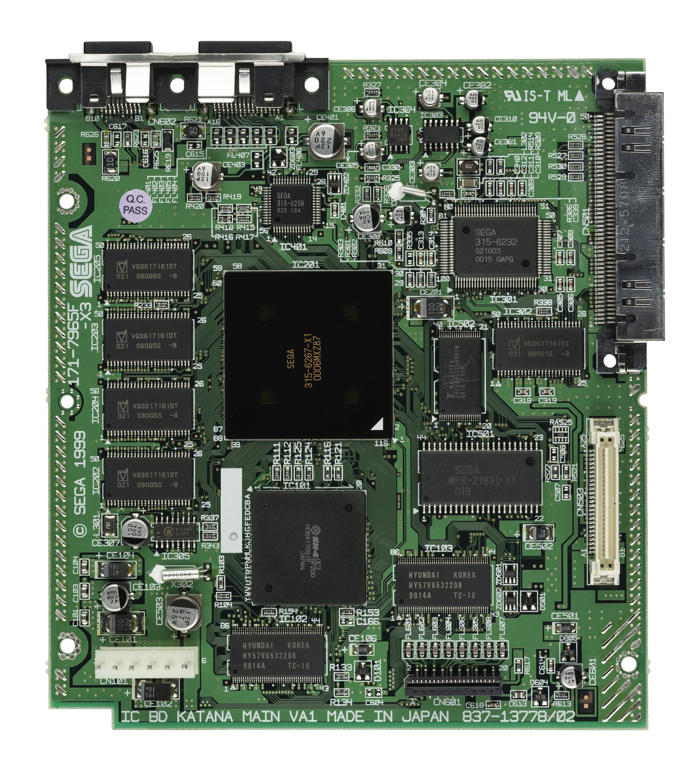
Identification
| Champ | Valeur |
|---|---|
| Fabricant | Sega |
| Sortie | 1998 (JP), 1999 (export) |
| Génération | 6e |
| Sortie vidéo | Composite, S-Video, RGB, VGA natif (VGA box) |
| Région / lockout | JP / US / EU (+ 50/60) |
| Média | GD-ROM (~1,2 Go) |
| Réseau | Modem intégré (SegaNet) |
Architecture (cousine de la NAOMI)
| Bloc | Puce | Fréquence | Notes |
|---|---|---|---|
| CPU | Hitachi SH-4 | 200 MHz | FPU/unité vectorielle (géométrie), ~360 MIPS |
| GPU | NEC/VideoLogic PowerVR2 (CLX2) | 100 MHz | Tile-Based Deferred Rendering (pas de Z-buffer plein écran) ; VGA 640×480 natif |
| Son | ARM7 (@ 45 MHz) + AICA (Yamaha) | 64 voies ; 2 Mo RAM son | |
| RAM | 16 Mo principale + 8 Mo VRAM + 2 Mo son | ||
| Média | Lecteur GD-ROM (~1,2 Go) | + modem 33,6k (SegaNet) |
→ Architecture quasi identique à la NAOMI arcade (mêmes SH-4/CLX2/AICA) — d'où les portages arcade↔Dreamcast quasi parfaits.
Manette, VMU & périphériques
- Manette : 2 slots d'extension recevant un VMU et/ou un Jump Pack (vibreur). Le câble sort par le bas (particularité de design).
- VMU (Visual Memory Unit) : carte mémoire avec écran LCD, D-pad et boutons — une mini-console (mini-jeux téléchargeables, affichage d'infos en jeu, ex. état de l'équipe dans les jeux de foot). Pile bouton propre.
- Périphériques : clavier + souris (Quake III, PSO, navigateur), micro (Seaman), maracas (Samba de Amigo), canne à pêche, arcade stick, pistolet.
- Réseau : modem 33,6k d'origine ; Broadband Adapter (BBA) et LAN Adapter (rares, chers) pour le haut débit.
Le GD-ROM & l'exploit MIL-CD (le point clé préservation)
La Dreamcast lit des GD-ROM (Gigabyte Disc, ~1,2 Go) : un CD à haute densité propriétaire (spirale gravée serrée sur la zone extérieure) que les graveurs grand public ne peuvent pas produire. En théorie, la copie était donc bloquée.
Mais la DC pouvait aussi démarrer des MIL-CD (Music Interactive Live-CD, un format CD interactif japonais) : ce chemin de boot avait une faille qui permettait à des CD-R auto-bootables de se lancer sans modchip. C'est la raison pour laquelle la Dreamcast a la réputation d'être « la plus facile à copier ».
Les VA1 tardives ont retiré le MIL-CD
À partir de ~octobre 2000, des cartes VA1 ont supprimé le support MIL-CD → ces consoles ne bootent plus les CD-R auto-bootables. Pour elles, il faut une autre voie : ODE (GDEMU/MODE), ou un boot disc (via l'exploit d'un jeu). Si tu vises le boot CD-R, cherche une VA0 ou une VA1 précoce ; sinon, l'ODE est de toute façon la voie de préservation la plus propre.
Révisions & pièces sensibles
- VA0 (early) puis VA1 (majorité) — implantation et alim différentes ; les VA1 tardives = pas de MIL-CD (voir ci-dessus).
- Pile RTC rechargeable (horloge/sauvegarde système) : sèche avec l'âge → l'horloge se réinitialise. La remplacer par un support + coin cell.
- Alim (PSU) : condos fatigués = redémarrages → recap ou DreamPSU/PicoPSU.
- VMU (Visual Memory Unit) : la carte mémoire à écran ; sa propre pile bouton s'épuise (mini-jeux/écran).
Pannes fréquentes
| Symptôme | Cause probable | Piste |
|---|---|---|
| Ne lit plus les GD | Laser usé | ODE (GDEMU/MODE) — recommandé |
| S'éteint / redémarre / bruit alim | Alim (PSU) — condos fatigués | Recap ou DreamPSU/PicoPSU |
| Horloge qui se réinitialise | Pile rechargeable HS | Remplacer (support + coin cell) |
| Ventilo bruyant | Ventilateur d'origine | Noctua + adaptateur |
| Pas d'image VGA | Jeu non VGA / câble | Vérifier compat VGA du jeu |
Procédures de démontage pas-à-pas ✅
10 procédures traduites depuis les guides iFixit, avec leur difficulté et leur durée estimée. Le titre d'origine est rappelé sous chaque procédure, pour retrouver le guide et ses photos.
| Procédure | Difficulté | Durée |
|---|---|---|
| Restauration cosmétique d'une manette (et d'un boîtier jauni) | 🟡 moyen | 1 à 2 days |
| Remplacement de la pile de sauvegarde | 🟡 moyen | 10 à 30 minutes |
| Remplacement du fusible F1 de la carte manette | 🟠 difficile | 10 à 20 minutes |
| Dépose de la baie d'extension | 🟢 très facile | 30 seconds |
| Remplacement du ventilateur | 🟢 facile | 10 minutes |
| Remplacement du lecteur GD-ROM | 🟡 moyen | 10 minutes |
| Dépose de la carte mère | 🟡 moyen | 20 à 45 minutes |
| Dépose du bloc d'alimentation | 🟡 moyen | 7 à 15 minutes |
| Remplacement de l'alimentation | 🟡 moyen | 30 à 45 minutes |
| Dépose du capot supérieur | 🟢 très facile | 1 à 5 minutes |
Restauration cosmétique d'une manette (et d'un boîtier jauni)
Nettoyage complet, déjaunissement au peroxyde sous UV (« retrobrite ») et lustrage d'une manette Dreamcast. La méthode vaut pour la plupart des boîtiers rétro en plastique clair. ⚠️ Compter 1 à 2 jours, l'essentiel étant du temps d'exposition.
- ⚠️ SÉCURITÉ — à lire avant de commencer. La crème utilisée pour le déjaunissement est du peroxyde d'hydrogène à 12 % (« 40 volumes »). C'est un produit corrosif : il brûle la peau et surtout les yeux. Gants et lunettes sont obligatoires, pas facultatifs comme le laisse entendre la source. Travaille dans un endroit ventilé et rince immédiatement à grande eau en cas de contact.
- ⚠️ Ne déjaunis jamais un plastique foncé ou coloré : le traitement en altère la teinte de façon irréversible.
- Nettoyage du câble. Gants aux mains, frotte le câble avec une lingette désinfectante, dans les deux sens — un seul sens ne suffit pas pour la saleté incrustée près du connecteur. Répète jusqu'à ce que la lingette ressorte propre.
- Pulvérise du nettoyant contact dans le connecteur pour garantir une bonne liaison au remontage.
- Démontage. La manette compte 8 vis : 6 extérieures et 2 intérieures.
- Retire les 6 vis extérieures au tournevis cruciforme n° 1 et dépose la coque arrière.
- Retire les 2 vis intérieures et dépose la carte électronique.
- Retire les 3 pastilles de caoutchouc et tous les boutons, et mets-les de côté.
- Facultatif : fais tremper les 8 vis dans de l'alcool à friction — elles ressortent comme neuves.
- Lavage des coques. À l'eau chaude et au savon antibactérien, à la main. Nettoie aussi l'intérieur.
- Si l'étiquette du dos compte pour toi, lave-la du bout des doigts, sans frotter.
- Les taches tenaces se retirent à l'outil plastique de démontage, qui ne raye pas. Le dissolvant est déconseillé.
- Déjaunissement. Étale du film alimentaire sur le plan de travail, assez grand pour envelopper la coque.
- Verse la crème peroxydée sur la coque et répartis-la aussi uniformément que possible — la forme irrégulière rend l'exercice délicat.
- Étale le surplus tombé sur le film.
- Retourne la coque et enveloppe-la complètement dans le film, sans laisser d'ouverture : la solution ne doit pas sécher.
- Pose l'ensemble dans un plat en aluminium ou en verre : la réflexion renvoie les UV sur les flancs et accélère nettement le traitement.
- Place le tout au plus près de la lampe UV, environ 30 cm.
- C'est cette étape qui prend 1 à 2 jours. Plus l'exposition est longue, meilleur est le résultat — surveille et arrête quand la teinte te convient.
- Nettoyage des pièces restantes. Boutons, pastilles de caoutchouc et support de carte mémoire, à l'eau chaude savonneuse. Une brosse à dents atteint les creux des lettres A/X/B/Y.
- ⚠️ Sur la pastille de la croix directionnelle, ne perds pas la petite pièce plastique centrale : sans elle, la croix ne fonctionne plus.
- Mets une crépine dans l'évier : une pièce partie dans la bonde est une pièce perdue.
- Laisse sécher les pastilles et le support à l'air libre.
- Lustrage. Applique le polish plastique au chiffon microfibre selon la notice, puis lustre. Trois passes donnent un bon résultat.
- Termine par un lavage au liquide vaisselle pour retirer les résidus de polish.
- Compte 1 h à 1 h 30 pour l'ensemble polissage, lustrage et rinçage.
- Nettoyage de l'électronique. Bracelet antistatique au poignet, pulvérise le nettoyant contact sur un coton-tige et frotte doucement la carte.
- Le joystick reste sur la carte, sauf à retirer ses 2 vis. Nettoie-le au coton-tige et à l'alcool, et brosse le dessous.
- Pulvérise du nettoyant dans les logements de carte mémoire, puis souffle à l'air sec.
- Fin du déjaunissement. Quand la durée d'exposition te convient, rince la coque au liquide vaisselle et sèche-la au papier absorbant.
- Si l'étiquette est au dos, tamponne, ne frotte pas : le support reste fragile tant qu'il n'est pas sec.
- Remontage. Vérifie que tout est parfaitement sec avant de remonter — un ventilateur ou de l'air sec accélèrent le séchage.
- ⚠️ Attention aux colonnettes de vis, elles cassent facilement. Si l'une casse, recolle-la à la colle cyanoacrylate.
- Facultatif : une fois remontée, passe un chiffon légèrement imprégné de polish sur l'ensemble.
- Retour d'expérience sur la méthode. Le plat réfléchissant sous la pièce fait une vraie différence : sans lui, le traitement est nettement plus long et les flancs sont mal atteints.
- Le sachet zip est plus rapide à mettre en place que le film, mais il enveloppe moins bien et le résultat est moins brillant. Le gain de temps (5 à 10 minutes) ne le justifie pas.
- Nettoyage des connecteurs de cartouche. Un peu d'alcool sur un tampon, frotter vigoureusement les contacts, puis lustrer à sec. Ne jamais utiliser de nettoyant liquide sur les cartouches de nettoyage à friction : cela réduit leur durée de vie.
- Poussière. Une housse anti-poussière est la protection la plus simple. Vérifie qu'elle laisse passer les câbles, sinon il faut la découper.
- Sur une console à cartouches exposée, laisse une cartouche vierge dans le port : c'est la plus grande ouverture par laquelle la poussière entre, et une cartouche vierge n'exerce aucune contrainte sur le connecteur.
- Traces de marqueur sur une cartouche. Une gomme magique en retire l'essentiel, puis finition à l'alcool sur un papier absorbant.
- ⚠️ Trop de pression use le fini du plastique : insiste progressivement plutôt que fort. Utilise des matériaux non abrasifs — coton-tiges, cotons, microfibre.
- Étiquettes. Des répliques d'étiquettes existent, mais elles diffèrent souvent légèrement de l'original (police, logo de classification) : compare avant d'acheter.
- ⚠️ N'utilise pas d'alcool à plus de 50 % sur une étiquette : au-delà, elle se délave. Peu de produit, peu de pression.
Titre d'origine : « Sega Dreamcast Controller Restoration/Retro Console Restoration ».
Remplacement de la pile de sauvegarde
Quand la Dreamcast redemande la date et l'heure à chaque allumage, sa pile de sauvegarde est morte. ⚠️ Cette réparation demande de souder.
- Vérifie que la console est débranchée du secteur avant de commencer.
- Retourne la console sur le dos.
- Relève le numéro de modèle, au cas où il faudrait commander des pièces.
- Retire la baie d'extension en appuyant sur son petit clip tout en la dégageant de la console.
- Repère et retire les quatre vis noires cruciformes n° 2 de 12 mm sous la console.
- La quatrième vis n'apparaît qu'une fois la baie d'extension retirée.
- Des éléments internes peuvent être libres : prends garde à ce qu'ils ne tombent pas en retirant le capot.
- Remets la console à l'endroit.
- Retire le capot supérieur en soulevant doucement la partie haute.
- Le câble blanc de la carte manette est fragile : vas-y doucement.
- Débranche le câble blanc en tirant doucement tout en le faisant jouer d'avant en arrière, jusqu'à ce qu'il se libère.
- Retire les quatre vis cruciformes n° 2 de 14 mm de la carte manette.
- Débranche le connecteur blanc du ventilateur du bloc des ports manette.
- Dépose la carte manette en la soulevant hors du bloc des ports.
- Repère bien où vont le + et le − avant de dessouder.
- Dessoude l'ancienne pile de la carte manette.
- Soude un support de pile à deux fils.
- Soude l'autre extrémité des fils sur la carte, en respectant les polarités relevées.
- Repose la carte manette.
- Fixe le support de pile à l'intérieur avec un adhésif double face en mousse.
- Insère la pile dans son support.
- Remonte la console en suivant les étapes à l'envers.
- Rebranche la console, allume-la et remets l'horloge à l'heure.
Titre d'origine : « Dreamcast CMOS Battery Replacement ».
Remplacement du fusible F1 de la carte manette
Remplacement du fusible F1 sur la carte des ports manette. ⚠️ Soudure indispensable. Le fusible se remplace soit par une résistance-fusible, soit par deux résistances de 10 Ω 1/4 W en parallèle.
- Vérifie que la console est débranchée du secteur avant de commencer.
- Retourne la console sur le dos.
- Relève le numéro de modèle, au cas où il faudrait commander des pièces.
- Retire la baie d'extension en appuyant sur son petit clip tout en la dégageant de la console.
- Repère et retire les quatre vis noires cruciformes n° 2 de 12 mm sous la console.
- La quatrième vis n'apparaît qu'une fois la baie d'extension retirée.
- Des éléments internes peuvent être libres : prends garde à ce qu'ils ne tombent pas en retirant le capot.
- Remets la console à l'endroit.
- Retire le capot supérieur en soulevant doucement la partie haute.
- Le câble blanc de la carte manette est fragile : vas-y doucement.
- Débranche le câble blanc en tirant doucement tout en le faisant jouer d'avant en arrière, jusqu'à ce qu'il se libère.
- Retire les quatre vis cruciformes n° 2 de 14 mm de la carte manette.
- Débranche le connecteur blanc du ventilateur du bloc des ports manette.
- Dépose la carte manette en la soulevant hors du bloc des ports.
- Retourne la carte manette, côté soudures vers toi.
- Dessoude le fusible F1 au fer et à la tresse à dessouder.
- F1 est clairement sérigraphié sur la face composants.
- Si le trou métallisé de F1 reste bouché, nettoie-le au fer et à la tresse.
- Si tu n'utilises pas de résistance-fusible, passe à l'étape suivante.
- Pose et soude la résistance-fusible neuve à l'emplacement F1. Elle se place côté composants, pattes traversant vers le côté soudures. Son sens n'a pas d'importance.
- Si tu viens de poser une résistance-fusible, saute l'étape suivante.
- Pose et soude deux résistances de 10 Ω 1/4 W en parallèle à l'emplacement F1. Elles se posent côté composants, pattes traversant. Leur sens n'a pas d'importance.
- ⚠️ Vérifie que les pattes ne touchent aucun autre composant côté composants : tu créerais un court-circuit à la mise sous tension.
Titre d'origine : « Sega Dreamcast Controller Port Replacement ».
Dépose de la baie d'extension
Comment retirer la baie d'extension de la Dreamcast.
- Vérifie que la console est débranchée du secteur avant de commencer.
- Retourne la console sur le dos.
- Relève le numéro de modèle, au cas où il faudrait commander des pièces.
- Retire la baie d'extension en appuyant sur son petit clip tout en la dégageant de la console.
Titre d'origine : « Sega Dreamcast Expansion Bay Replacement ».
Remplacement du ventilateur
Comment remplacer un ventilateur défaillant. Prends-en un correspondant à ton numéro de modèle.
- Vérifie que la console est débranchée du secteur avant de commencer.
- Retourne la console sur le dos.
- Relève le numéro de modèle, au cas où il faudrait commander des pièces.
- Retire la baie d'extension en appuyant sur son petit clip tout en la dégageant de la console.
- Repère et retire les quatre vis noires cruciformes n° 2 de 12 mm sous la console.
- La quatrième vis n'apparaît qu'une fois la baie d'extension retirée.
- Des éléments internes peuvent être libres : prends garde à ce qu'ils ne tombent pas en retirant le capot.
- Remets la console à l'endroit.
- Retire le capot supérieur en soulevant doucement la partie haute.
- Débranche le connecteur blanc du ventilateur en le tirant doucement hors du bloc des ports manette.
- Il est peut-être déjà débranché si tu as suivi la procédure de dépose des ports manette.
- Retire les deux vis cruciformes n° 00 de 8,5 mm du support de ventilateur.
- Retire les deux vis cruciformes n° 00 de 17,5 mm du support.
- Dépose le ventilateur de son support.
- Fixe le ventilateur neuf sur son support avec les deux vis cruciformes n° 00 de 17,5 mm.
- Repose le support dans la console avec les deux vis cruciformes n° 00 de 8,5 mm.
Titre d'origine : « Sega Dreamcast Fan Replacement ».
Remplacement du lecteur GD-ROM
Comment remplacer un lecteur GD-ROM défaillant. Prends-en un correspondant à ton numéro de modèle.
- Vérifie que la console est débranchée du secteur avant de commencer.
- Retourne la console sur le dos.
- Relève le numéro de modèle, au cas où il faudrait commander des pièces.
- Retire la baie d'extension en appuyant sur son petit clip tout en la dégageant de la console.
- Repère et retire les quatre vis noires cruciformes n° 2 de 12 mm sous la console.
- La quatrième vis n'apparaît qu'une fois la baie d'extension retirée.
- Des éléments internes peuvent être libres : prends garde à ce qu'ils ne tombent pas en retirant le capot.
- Remets la console à l'endroit.
- Retire le capot supérieur en soulevant doucement la partie haute.
- Débranche la nappe orange en tirant doucement tout en la faisant jouer, jusqu'à ce qu'elle se libère de la carte mère.
- Débranche les trois câbles du GD-ROM de la carte mère.
- Retire les deux vis noires cruciformes n° 2 de 12 mm sur le côté gauche du support du GD-ROM.
- Sur la première photo la console est tournée d'un quart de tour à gauche ; la seconde la montre en position normale.
- En soulevant le GD-ROM, prends garde à ce que la moitié haute du bloc ne se sépare pas de sa base.
- Dépose le GD-ROM en le soulevant doucement de sa base.
- Remplace le GD-ROM défaillant par un exemplaire fonctionnel.
- Fixe le lecteur neuf avec les vis cruciformes n° 2.
- Rebranche les trois câbles du GD-ROM à la carte mère.
- Rebranche la nappe de données du GD-ROM à la carte mère.
Titre d'origine : « Sega Dreamcast GD-ROM Replacement ».
Dépose de la carte mère
Comment déposer la carte mère de la Dreamcast.
- Vérifie que la console est débranchée du secteur avant de commencer.
- Retourne la console sur le dos.
- Relève le numéro de modèle, au cas où il faudrait commander des pièces.
- Retire la baie d'extension en appuyant sur son petit clip tout en la dégageant de la console.
- Repère et retire les quatre vis noires cruciformes n° 2 de 12 mm sous la console.
- La quatrième vis n'apparaît qu'une fois la baie d'extension retirée.
- Des éléments internes peuvent être libres : prends garde à ce qu'ils ne tombent pas en retirant le capot.
- Remets la console à l'endroit.
- Retire le capot supérieur en soulevant doucement la partie haute.
- ⚠️ Vérifie que la console est débranchée. Si tu viens de l'éteindre, laisse quelques minutes aux condensateurs pour se décharger avant d'intervenir.
- Débranche le connecteur femelle blanc en pinçant son clip et en le tirant doucement hors de la carte d'alimentation.
- Retire les deux vis cruciformes n° 2 de 10 mm du bloc d'alimentation.
- Ne tords pas les broches mâles du connecteur en dégageant l'alimentation du châssis.
- Dépose la carte d'alimentation à deux mains, en la soulevant doucement.
- Retire le film plastique transparent glissé entre l'alimentation et le châssis.
- Le câble blanc de la carte manette est fragile : vas-y doucement.
- Débranche le câble blanc en tirant doucement tout en le faisant jouer d'avant en arrière, jusqu'à ce qu'il se libère.
- Retire les quatre vis cruciformes n° 2 de 14 mm de la carte manette.
- Débranche le connecteur blanc du ventilateur du bloc des ports manette.
- Dépose la carte manette en la soulevant hors du bloc des ports.
- Débranche la nappe orange en tirant doucement tout en la faisant jouer, jusqu'à ce qu'elle se libère de la carte mère.
- Débranche les trois câbles du GD-ROM de la carte mère.
- Retire les deux vis noires cruciformes n° 2 de 12 mm sur le côté gauche du support du GD-ROM.
- Sur la première photo la console est tournée d'un quart de tour à gauche ; la seconde la montre en position normale.
- En soulevant le GD-ROM, prends garde à ce que la moitié haute du bloc ne se sépare pas de sa base.
- Dépose le GD-ROM en le soulevant doucement de sa base.
- Débranche le connecteur blanc du ventilateur en le tirant doucement hors du bloc des ports manette.
- Il est peut-être déjà débranché si tu as suivi la procédure de dépose des ports manette.
- Retire les deux vis cruciformes n° 00 de 8,5 mm du support de ventilateur.
- Retire les deux vis cruciformes n° 00 de 17,5 mm du support.
- Dépose le ventilateur de son support.
- Retire les cinq vis cruciformes n° 2 de 10 mm du côté gauche du capot de la carte mère.
- Retire les trois vis noires cruciformes n° 2 de 12 mm du côté droit.
- Soulève le capot métallique hors de la console.
- Avant de manipuler la carte mère, mets un bracelet antistatique. À défaut, décharge-toi en touchant une grande masse métallique.
- Dépose la carte mère et pose-la sur une surface antistatique.
Titre d'origine : « Sega Dreamcast Logic Board Replacement ».
Dépose du bloc d'alimentation
Comment déposer le bloc d'alimentation de la Dreamcast.
- Vérifie que la console est débranchée du secteur avant de commencer.
- Retourne la console sur le dos.
- Relève le numéro de modèle, au cas où il faudrait commander des pièces.
- Retire la baie d'extension en appuyant sur son petit clip tout en la dégageant de la console.
- Repère et retire les quatre vis noires cruciformes n° 2 de 12 mm sous la console.
- La quatrième vis n'apparaît qu'une fois la baie d'extension retirée.
- Des éléments internes peuvent être libres : prends garde à ce qu'ils ne tombent pas en retirant le capot.
- Remets la console à l'endroit.
- Retire le capot supérieur en soulevant doucement la partie haute.
- ⚠️ Vérifie que la console est débranchée. Si tu viens de l'éteindre, laisse quelques minutes aux condensateurs pour se décharger avant d'intervenir.
- Débranche le connecteur femelle blanc en pinçant son clip et en le tirant doucement hors de la carte d'alimentation.
- Retire les deux vis cruciformes n° 2 de 10 mm du bloc d'alimentation.
- Ne tords pas les broches mâles du connecteur en dégageant l'alimentation du châssis.
- Dépose la carte d'alimentation à deux mains, en la soulevant doucement.
- Retire le film plastique transparent glissé entre l'alimentation et le châssis.
Titre d'origine : « Replacing Sega Dreamcast Power Block (Power Supply) ».
Remplacement de l'alimentation
Comment remplacer une alimentation défaillante par une alimentation fonctionnelle.
- Vérifie que la console est débranchée du secteur avant de commencer.
- Retourne la console sur le dos.
- Relève le numéro de modèle, au cas où il faudrait commander des pièces.
- Retire la baie d'extension en appuyant sur son petit clip tout en la dégageant de la console.
- Repère et retire les quatre vis noires cruciformes n° 2 de 12 mm sous la console.
- La quatrième vis n'apparaît qu'une fois la baie d'extension retirée.
- Des éléments internes peuvent être libres : prends garde à ce qu'ils ne tombent pas en retirant le capot.
- Remets la console à l'endroit.
- Retire le capot supérieur en soulevant doucement la partie haute.
- ⚠️ Débranche la console. Si tu viens de l'éteindre, laisse quelques minutes aux condensateurs pour se décharger.
- Débranche le connecteur femelle blanc en le pinçant et en le tirant droit vers le haut.
- Retire les deux vis cruciformes n° 2 de la carte.
- Dépose la carte d'alimentation à deux mains, sans abîmer les broches mâles.
- Sors le bloc en le saisissant par les bords et en le soulevant droit.
- Retire les deux vis cruciformes n° 2 de 10 mm pour détacher le module interrupteur de la console.
- Procure-toi une carte d'alimentation de remplacement.
Titre d'origine : « Sega Dreamcast Power Supply Replacement ».
Dépose du capot supérieur
Comment retirer le capot supérieur de la Dreamcast.
- Vérifie que la console est débranchée du secteur avant de commencer.
- Retourne la console sur le dos.
- Relève le numéro de modèle, au cas où il faudrait commander des pièces.
- Retire la baie d'extension en appuyant sur son petit clip tout en la dégageant de la console.
- Repère et retire les quatre vis noires cruciformes n° 2 de 12 mm sous la console.
- La quatrième vis n'apparaît qu'une fois la baie d'extension retirée.
- Des éléments internes peuvent être libres : prends garde à ce qu'ils ne tombent pas en retirant le capot.
- Remets la console à l'endroit.
- Retire le capot supérieur en soulevant doucement la partie haute.
Titre d'origine : « Sega Dreamcast Top Cover Replacement ».
Source, licence et portée
Guides iFixit, sous Creative Commons BY-NC-SA — attribution, usage non commercial, partage à l'identique. Le texte est traduit de l'anglais ; le titre d'origine est rappelé sous chaque procédure et les photos d'étapes restent sur iFixit. ⚠️ Ces guides visent le modèle nommé dans le titre : sur une autre révision, la visserie et l'ordre de dépose peuvent différer.
Procédure — console morte, dans l'ordre ✅
Ce que cette procédure ajoute
Un ordre pensé pour une console, pas pour une carte arcade : ce qui tue ces machines n'est presque jamais le CPU. C'est, dans l'ordre réel, l'alimentation, les condensateurs, le lecteur ou le slot de cartouche, et la logique seulement ensuite. → Diagnostic PCB
1. L'alimentation. Deux cas selon la machine. Bloc externe : ⚠️ lire le marquage sur la machine, à côté de la prise, et vérifier l'adaptateur en face — tension et polarité. Une machine à centre négatif alimentée en centre positif y laisse son fusible, parfois son régulateur ; ne pas se fier à l'étiquette d'un bloc tiers ni à un embout universel. Alimentation interne (la machine se branche directement au secteur) : le secteur est dans le boîtier. Débrancher, attendre, et vérifier que les gros condensateurs sont déchargés avant de toucher la carte. Dans les deux cas, mesurer en charge : un bloc fatigué tient sa tension jusqu'à ce qu'on lui demande du courant.
2. Le fusible. Beaucoup de ces machines en ont un juste derrière la prise — c'est la pièce faite pour mourir. Le tester en continuité, hors circuit. Un fusible qui resaute est un court-circuit, pas un problème de fusible.
3. Les condensateurs. Sur la plupart des machines de cet âge, c'est le suspect par défaut et non le dernier recours — les électrolytiques CMS qui fuient rongent les pistes dessous avant de donner le moindre autre signe. ⚠️ Toutes n'en sont pas là : certaines en portent très peu et ne se recappent pas par principe. Lire ce que cette page en dit avant de sortir le fer. → Recap
4. Le lecteur. Sur cette machine, c'est le poste de panne dominant. Dans l'ordre : le plateau/tiroir bouge-t-il, le disque tourne-t-il, la lentille est-elle propre (coton-tige, alcool isopropylique, sans appuyer), les rails coulissent-ils librement. Un laser qui ne lit plus se remplace ; le potentiomètre de gain ne se retouche pas à l'aveugle, c'est le geste qui achève un laser encore bon.
5. La sortie vidéo. Isoler la machine de l'affichage : un autre câble, une autre télé, une autre entrée. Une part non négligeable des « consoles mortes » est un câble mort, ou un afficheur qui n'accroche pas ce que la machine sort — voir la section vidéo de cette page pour savoir quoi.
6. Toujours rien. Maintenant, et seulement maintenant, la logique : rails sur la carte, reset, horloge, bus. → Diagnostic PCB
Mods populaires — quoi acheter, où, procédures
Repère de carte (crucial pour l'ODE)
Le repère VA0 / VA1 (au dos) compte : un GDEMU se pose directement sur une VA1 (le plus courant), mais une VA0 demande le « GDEMU in VA0 Mod » (adaptation). Procédures d'après ConsoleMods (CC-BY-SA). Soudure : 🟢 aucune · 🟡 · 🟠 · 🔴.
Jeux sur SD — ODE (remplacer le lecteur GD-ROM)
- GDEMU (MNEMO) — carte qui remplace le lecteur GD-ROM : jeux depuis carte SD, plug-in 🟢 sur VA1 (connecteur du lecteur). Ajoute un GDEMU SD Tray (trappe propre en façade). VA0 → voir la note.
- USB-GDROM (SD/USB) et MODE (Terraonion) = alternatives. → fiche GDEMU / MODE.
Vidéo
- VGA natif : la DC sort du VGA RVBHV superbe via une VGA box / câble — le meilleur analogique (⚠️ certains jeux forcent le 15 kHz, voir la liste des jeux VGA + patchs).
- HDMI : DCHDMI (PixelFX) — install interne (nappe sur le bus vidéo), image parfaite ; Retro GEM.
Fiabilité — alim, ventilo, pile
- Alim de remplacement : l'alim d'origine chauffe/vieillit → DreamPSU / PicoDreamcast (module régulé). → Remplacer l'alim.
- Noctua Fan Mod : remplace le ventilo bruyant par un Noctua 40 mm (souvent via un step-down 12→5V) — silence.
- Pile de sauvegarde/RTC : la ML2032 rechargeable soudée meurt (date/heure perdues) → Replaceable Battery Mod (porte-pile + CR2032). Recap de l'alim + kit condensateurs sur les modèles concernés.
Région / dézonage
- Le plus simple (0 soudure) : un boot disc region-free (utopia…) depuis le lecteur ou l'ODE.
- Region Frequency Mod 🟡 : ponter les pastilles de R422 (au dos de la carte) → la DC bascule sur la bonne région/fréquence du jeu (sinon image N&B ou décentrée sur un jeu d'une autre région).
- BIOS Replacement Mod 🟠 : remplacer la puce BIOS → region-free + MIL-CD, boot backups gravés (VA2), VGA forcé. Points exacts ci-dessous.
BIOS Replacement (region-free) — points exacts (transcrit de ConsoleMods, CC-BY-SA)
Deux firmwares au choix : le BIOS d'origine patché region-free + MIL-CD, ou le Japanese Cake BIOS (plus d'options : couleur d'anim, écran licence SEGA on/off, MIL-CD).
- Repérer la puce BIOS IC501 (marquée MPR-21931-X1, MPR-21933-X1 ou MPR-21931-X2).
- Contrôle tension : allumer, mesurer la broche 23 au multimètre → ~3,3 V = puce BIOS 3,3 V, ~5 V = puce 5 V (prendre la bonne).
- Dessouder l'ancienne puce, souder la nouvelle.
- Fil de la broche 1 de la nouvelle BIOS vers la broche 23.
- Write-enable (pour pouvoir mettre à jour le BIOS par soft plus tard) : fil de la broche 44 de la nouvelle BIOS vers la broche B14 du connecteur GD-ROM.
- Nettoyer à l'alcool iso, tester (caler l'ODE/GD-ROM bien à plat), puis faire le Region Frequency Mod (R422) ci-dessus pour corriger d'éventuels soucis d'image. (Guide d'origine : Dennis van den Broek.)
Homebrew / préservation
- Charger du homebrew : DreamShell (loader SD) ; SDK KallistiOS. La DC reçoit encore des sorties indépendantes. Serveurs en ligne : officiels fermés → serveurs communautaires (Dreamcast Live) pour PSO & co. Émulation : Flycast (partagé avec la NAOMI), Redream.
Photos / assets
(À ajouter : carte mère, alim, lecteur GD, VGA out.)
Réparation avancée
Lecteur GD-ROM (souvent remplacé par GDEMU) + pile RTC + recap (alim). Méthodes : ODE (GDEMU) · Piles de sauvegarde · Recap · Diagnostic PCB.
Documentation constructeur archivée ✅
Documentation constructeur archivée localement. ⚠️ Ce sont des manuels d'utilisation et de référence, pas des manuels de service : ils donnent les caractéristiques, les connecteurs et le fonctionnement attendu, mais pas les schémas ni les tensions de dépannage.
- Dreamcast — PDF
Statut
Documents constructeur sans licence explicite, conservés à titre de préservation (machines hors production depuis des décennies).
Sources & attribution
- Wikipédia — Dreamcast — CC-BY-SA — https://fr.wikipedia.org/wiki/Dreamcast
- ConsoleMods — Dreamcast : Region Frequency Mod (ponter R422) + BIOS Replacement Mod (IC501 MPR-21931/21933, tension br.23, fil br.1→br.23, write-enable br.44→GD-ROM B14) — CC-BY-SA — https://consolemods.org/wiki/Dreamcast:BIOS_Replacement_Mod
Image :
-
dreamcast-board.jpg— Evan-Amos, domaine public — https://commons.wikimedia.org/wiki/File:Sega-Dreamcast-Motherboard-Top.jpg

Relecture & corrections
À quoi sert cet espace
Une valeur fausse, une procédure dépassée, une référence de puce qui ne colle pas à ta carte ? Signale-le ici, avec ce que tu as constaté (modèle, révision de carte, numéro de série, mesure). Chaque signalement est recoupé avec une source avant toute modification — une correction invérifiable est publiée en tant que « signalé par …, non recoupé » plutôt qu'appliquée en silence.
La lecture est ouverte à tous ; écrire demande une connexion Discord. Les signalements des relecteurs déclarés du wiki sont traités en priorité ; les autres sont lus aussi, mais passent par un humain avant toute modification.