Nintendo Wii
Console de Nintendo (2006), rétrocompatible GameCube. CPU PowerPC « Broadway », GPU ATI « Hollywood ». Sa force pour la préservation : elle est softmoddable (Homebrew Channel, sans mod matériel) — region-free, USB loaders, sauvegardes.
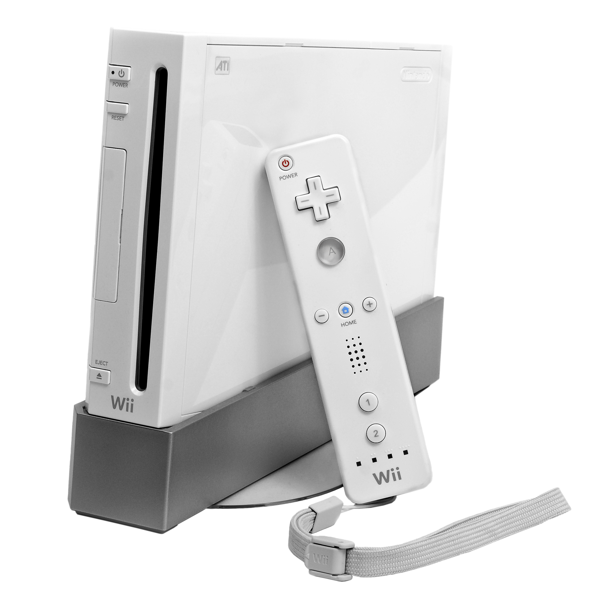
Identification
| Champ | Valeur |
|---|---|
| Fabricant | Nintendo |
| Sortie | 2006 |
| Génération | 7e |
| Rétrocompat | GameCube (modèles RVL-001) |
| Sortie vidéo | Composite, S-Video, RGB natif (Péritel), Component (480p) — pas de HDMI natif |
| Média | DVD (Wii + disques GC) |
Architecture (détail)
| Bloc | Puce | Fréquence | Notes |
|---|---|---|---|
| CPU | PowerPC Broadway (successeur du Gekko) | 729 MHz | |
| GPU | ATI Hollywood | 243 MHz | intègre 3 Mo eDRAM + 24 Mo 1T-SRAM |
| RAM | 24 Mo 1T-SRAM + 64 Mo GDDR3 | ||
| Sécurité | coprocesseur Starlet (ARM, dans Hollywood) | cible des exploits softmod |
La rétrocompat GameCube est native (le Broadway est un Gekko « overclocké ») : les modèles RVL-001 ont les ports manettes + carte mémoire GC et lisent les mini-DVD GameCube. Les révisions RVL-101 (Family Edition) puis Wii mini les suppriment.
RGB natif : PAL seulement
Comme la plupart des consoles Nintendo de l'époque, la Wii ne sort du RGB Péritel que sur les modèles PAL. Les Wii NTSC ne délivrent pas de RGB analogique — il faut passer par le Component (YPbPr, 480p) ou un mod HDMI numérique interne.
Historique des exploits (softmod)
La préservation Wii repose sur une chaîne d'exploits logiciels (aucun matériel) : Twilight Hack (via Zelda: Twilight Princess), Bannerbomb, puis LetterBomb (via un message de la chaîne d'accueil, dépend de l'adresse MAC) et str2hax (par les réglages réseau). Ils installent le Homebrew Channel et BootMii (sauvegarde/restauration de la NAND — filet de sécurité contre le brick). C'est cette accessibilité qui fait de la Wii une plateforme de préservation de choix.
Manettes & accessoires
- Wii Remote : accéléromètre + pointeur infrarouge (la « Sensor Bar » n'est qu'une barre de LED IR — remplaçable par deux bougies !). Nunchuk (accéléromètre + stick).
- MotionPlus : dongle gyroscope (précision 1:1), intégré dans la Wii Remote Plus.
- Classic Controller / Classic Controller Pro (jeux VC/rétro), Balance Board (Wii Fit), Wii Wheel, Zapper.
- Services (fermés) : WiiConnect24, Wii Shop / Console Virtuelle.
- ⚠️ Le « vWii » (mode Wii de la Wii U) est une autre machine — ne pas confondre.
Pannes & maintenance
- Console fiable ; le point faible est le lecteur DVD (usure).
- Recap secondaire.
- Modèle Wii mini / Family Edition (RVL-101) : sans lecteur GC ni certaines sorties.
Procédures de démontage pas-à-pas ✅
17 procédures traduites depuis les guides iFixit, avec leur difficulté et leur durée estimée. Le titre d'origine est rappelé sous chaque procédure, pour retrouver le guide et ses photos.
| Procédure | Difficulté | Durée |
|---|---|---|
| Écran noir — ce qu'il faut vérifier avant d'ouvrir | 🟢 très facile | 1 à 20 minutes |
| Démontage intégral (teardown) | 🟡 moyen | 1 à 2 heures |
| Remplacement de la carte Bluetooth | 🟡 moyen | 30 minutes à 1 heure |
| Remplacement de la coque inférieure | 🟡 moyen | non estimée |
| Remplacement du lecteur | 🟡 moyen | 1 à 2 heures |
| Remplacement du lecteur (variante condensée) | — | — |
| Remplacement de la lentille du lecteur | 🟡 moyen | 1 à 2 heures |
| Entretien du lecteur (RVL-001) | 🟡 moyen | 15 minutes à 3 heures |
| Remplacement des fusibles de la carte lecteur | 🔴 très difficile | 45 minutes |
| Remplacement de la façade | 🟡 moyen | 5 à 15 minutes |
| Remplacement du ventilateur | 🟡 moyen | 30 minutes à 1 heure |
| Remplacement du dissipateur | 🟡 moyen | 45 minutes à 2 heures |
| Remplacement de la carte mère | 🟡 moyen | 1 à 3 heures |
| Dépose du capot de carte mère | — | — |
| Dépose de la coque | 🟡 moyen | 20 à 40 minutes |
| Remplacement des antennes Wi-Fi | 🟡 moyen | 30 minutes à 1 heure |
| Remplacement de la carte Wi-Fi | 🟡 moyen | 35 à 45 minutes |
Écran noir — ce qu'il faut vérifier avant d'ouvrir
Avant de démonter une Wii qui n'affiche rien, une série de vérifications simples règle la majorité des cas.
- Vérifie d'abord que la console est bien allumée — la panne la plus fréquente n'en est pas une.
- Vérifie que le téléviseur est sur la bonne entrée.
- Sur une Wii Mini (noire et rouge, chargement par le dessus), vérifie que tu utilises bien un câble A/V composite (fiches rouge, blanche et jaune) : elle ne gère pas les autres formats.
- Vérifie que les fiches sont enfoncées à fond des deux côtés, et que les couleurs correspondent.
- Les prises fatiguées ont parfois besoin qu'on remue légèrement la fiche pour retrouver le contact.
- Teste un autre câble A/V si tu en as un, pour écarter le câble en cause.
- Teste la console sur un autre téléviseur : cela départage la console du téléviseur en une minute.
- Si tu soupçonnes un mauvais réglage d'affichage, tu peux naviguer à l'aveugle dans les menus, en connaissant leur enchaînement.
- Débranche la console du secteur quelques secondes, puis rebranche : cela réinitialise l'étage vidéo.
- Enfin, vérifie les réglages du téléviseur : un zoom ou un recadrage actif peut masquer l'image.
Titre d'origine : « Blank Screen Repair Techniques ».
Démontage intégral (teardown)
Démontage complet d'une Wii, du boîtier à la carte mère. ⚠️ Attention : sur iFixit, la procédure « Servicing the Nintendo Wii (RVL-001) disc drive » porte exactement le même texte que ce démontage, sous un autre identifiant. Ce n'est pas une erreur de transcription : les deux guides sont réellement identiques à la source.
- Débranche tous les câbles externes de la console.
- Rassemble les outils.
- Une petite vis retient la pile de sauvegarde.
- Cette vis retirée, le tiroir plastique coulisse hors de la console.
- Retire les trois vis noires du boîtier — celle de droite est un peu plus longue. Elles tiennent le cache plastique noir des ports manette.
- Retire le cache plastique noir.
- Quatre vis suivent : deux cruciformes n° 00 et deux Tri-wing.
- Retire toutes les vis du boîtier.
- Certaines sont sous les pieds caoutchouc ou sous de petits caches papier carrés : soulève-les avec un outil métallique fin.
- Plusieurs vis du boîtier demandent un tournevis Tri-wing.
- Les pieds et les caches sont autocollants mais réutilisables : mets-les de côté.
- Retire les pieds caoutchouc et les vis qu'ils cachent.
- ⚠️ Si tu tires sur la façade avant d'avoir retiré ces vis, la patte de fixation casse.
- Toutes les vis retirées, la façade du lecteur se dégage.
- Le câble reliant la façade se débranche doucement à la main ou au spudger.
- Le boîtier peut alors être séparé.
- Retire les six vis cruciformes n° 00 du capot du lecteur optique.
- Un câble étant fixé au lecteur, il est plus commode de remettre le capot pour déposer le bloc lecteur entier d'un seul tenant.
- Le lecteur contient beaucoup de pièces, mais rien d'inhabituel pour un lecteur à fente.
- Les vis qui le retiennent sont profondément logées dans le châssis.
- Ces vis retirées, le bloc entier se soulève.
- ⚠️ Ne tire pas trop fort : deux câbles relient encore le lecteur à la carte mère.
- Un câble coulisse hors de sa fente horizontale ; la nappe suit.
- Ces câbles débranchés, le lecteur se retire complètement.
- Retire ensuite le petit encadrement plastique noir pour accéder à la carte mère.
- À l'intérieur, toutes les vis sont cruciformes n° 00. Elles sont repérées sur la carte par des flèches, triangles, carrés et croix.
- Retire toutes les vis du capot de carte mère : deux en creux au centre, les autres sur le pourtour — d'autres apparaissent au fur et à mesure.
- ⚠️ Deux fils fragiles relient la carte mère aux antennes Wi-Fi : ne tire pas dessus.
- Retire les vis du carter plastique noir.
- Détache le ventilateur — deux vis le retiennent.
- Débranche son connecteur d'alimentation pour le retirer complètement.
- Si ton tournevis n'est pas aimanté, tiens un aimant contre la tige pour extraire les vis logées au fond.
- Toutes les vis retirées, le carter noir se dégage.
- Les carters retirés, tous les trous de vis deviennent visibles.
- ⚠️ Au moins une pièce est collée au capot par un pad thermique : prévois de le remplacer, ou décolle-le avec précaution.
- Retire les vis restantes du capot de carte mère.
- Soulève le capot.
- Le pad thermique est maintenant visible.
- Le dissipateur peut être déposé, mais ce n'est pas nécessaire pour aller plus loin.
- 💡 Un moule à muffins est très pratique pour trier les vis par étape — elles sont nombreuses et de longueurs différentes.
- Le remontage prend environ une demi-heure.
Titre d'origine : « Nintendo Wii Teardown ».
Remplacement de la carte Bluetooth
Dépose de la carte Bluetooth, qui gère les manettes.
- Avec un spudger métallique, retire les caches de vis en plastique blanc collés sur la coque inférieure, à l'avant.
- Retire les deux vis Tri-wing de 8,3 mm cachées dessous.
- Retire l'unique vis cruciforme de 5,9 mm sous la trappe de port manette la plus proche de la façade.
- Avec un spudger métallique, retire le pied caoutchouc collé sur le flanc, près de la fente du lecteur.
- Retire l'unique vis cruciforme de 5,9 mm cachée dessous.
- Écarte doucement la façade de l'avant de la Wii.
- À la pince à épiler, débranche le connecteur plastique du câble de LED de la carte mère.
- Retire la façade.
- Ouvre la trappe de port manette jusqu'à ce qu'elle soit perpendiculaire à l'entourage noir.
- Tire la trappe droit vers le haut pour la libérer de la coque.
- Répète l'opération pour la trappe du lecteur de carte mémoire.
- Retire les deux vis cruciformes de 4,1 mm restantes le long du bord supérieur de l'entourage noir.
- Soulève l'entourage par son grand côté le plus éloigné des ports et retire-le.
- Retire les deux vis cruciformes de 5 mm au-dessus des ports manette.
- Avec un spudger métallique, retire les trois caches de vis collés sur le flanc.
- Retire les vis suivantes :
- Deux vis cruciformes de 5 mm.
- Une vis Tri-wing de 8,2 mm.
- Avec un spudger métallique, retire les deux pieds caoutchouc sous la console, près des connecteurs arrière.
- Retire les deux vis Tri-wing de 8,2 mm cachées dessous.
- Une douille de 4 mm permet de rallonger l'embout pour atteindre les vis au fond des lamages.
- Soulève la coque droit vers le haut pour la dégager du corps de la Wii.
- Retire la petite vis cruciforme qui tient la trappe de pile à la coque inférieure — elle est imperdable, solidaire de la trappe.
- Sors la trappe de pile.
- ⚠️ L'heure système sera réinitialisée dès que la trappe est retirée.
- C'est le bon moment pour changer la pile CR2032 si ce n'est pas déjà fait.
- Retire la vis Tri-wing de 8,2 mm qui était cachée sous la trappe.
- Retire les deux vis Tri-wing de 8,2 mm qui tiennent le blindage du lecteur, près des ports manette.
- ⚠️ Les bords du blindage sont coupants : manipule-le avec précaution.
- Soulève le blindage du lecteur et retire-le.
- Retire les quatre vis cruciformes de 9 mm qui fixent le lecteur à la coque inférieure.
- Soulève le côté du lecteur opposé aux ports manette, assez pour atteindre les câbles sous sa face inférieure.
- Dégage doucement le câble d'alimentation du lecteur de sous le carénage plastique, près du dissipateur.
- Débranche le câble d'alimentation du lecteur.
- Avec l'ongle, relève le volet de maintien du connecteur de nappe du lecteur.
- ⚠️ Fais levier sur le volet, pas sur le connecteur lui-même.
- Sors la nappe de son connecteur.
- Retire le lecteur de la Wii.
- À la pince à épiler, sors le connecteur du ventilateur de son embase sur la carte mère.
- ⚠️ Pince le connecteur, pas l'embase soudée à la carte.
- Retire les deux vis cruciformes de 10 mm qui tiennent le ventilateur à son carénage.
- Retire le ventilateur.
- Avec la pointe d'un spudger, dégage l'une des pattes plastique noires du carénage.
- Sors l'antenne Wi-Fi du carénage.
- Retire l'unique vis cruciforme de 10 mm de la seconde antenne, sur le dessus du carénage.
- Retire les deux morceaux d'adhésif qui tiennent le câble de la seconde antenne au support près du dissipateur.
- Dégage soigneusement les deux antennes du châssis et mets-les de côté.
- Retire les trois vis cruciformes de 10 mm qui fixent le carénage.
- Soulève le carénage hors du dissipateur et retire-le.
- Retire les six vis qui fixent les languettes de blindage à la coque inférieure :
- Quatre vis cruciformes de 7 mm.
- Deux vis cruciformes de 11,3 mm.
- Retire les deux jeux de languettes de blindage.
- Retire les trois vis suivantes :
- Une vis cruciforme de 7 mm.
- Deux vis cruciformes de 10 mm.
- Sors le support.
- Retire les trois vis cruciformes de 10 mm du support noir, près de l'avant.
- Soulève légèrement le support et, de l'autre main, écarte le clip de maintien à l'endroit où les antennes entrent dans le blindage.
- Retire le support.
- ⚠️ Ne perds pas le petit écrou carré logé sans serrage dans le support noir.
- Retire les neuf vis cruciformes de 7 mm restantes qui fixent le capot de carte mère.
- Soulève le capot avec précaution, en surveillant les câbles.
- Sur certains modèles, un pad thermique pour la puce sans fil est collé sous le capot : pense à le remettre au remontage.
- Avec le côté plat d'un spudger ou aux doigts, soulève l'extrémité de la carte Bluetooth la plus proche du centre de la carte mère.
- Décolle doucement son bord avant de la mousse anti-interférences.
- Retire la carte Bluetooth.
Titre d'origine : « Nintendo Wii Bluetooth Board Replacement ».
Remplacement de la coque inférieure
Dépose de la coque inférieure : elle suppose d'avoir vidé la console de tous ses organes.
- Avec un spudger métallique, retire les caches de vis en plastique blanc collés sur la coque inférieure, à l'avant.
- Retire les deux vis Tri-wing de 8,3 mm cachées dessous.
- Retire l'unique vis cruciforme de 5,9 mm sous la trappe de port manette la plus proche de la façade.
- Avec un spudger métallique, retire le pied caoutchouc collé sur le flanc, près de la fente du lecteur.
- Retire l'unique vis cruciforme de 5,9 mm cachée dessous.
- Écarte doucement la façade de l'avant de la Wii.
- À la pince à épiler, débranche le connecteur plastique du câble de LED de la carte mère.
- Retire la façade.
- Ouvre la trappe de port manette jusqu'à ce qu'elle soit perpendiculaire à l'entourage noir.
- Tire la trappe droit vers le haut pour la libérer de la coque.
- Répète l'opération pour la trappe du lecteur de carte mémoire.
- Retire les deux vis cruciformes de 4,1 mm restantes le long du bord supérieur de l'entourage noir.
- Soulève l'entourage par son grand côté le plus éloigné des ports et retire-le.
- Retire les deux vis cruciformes de 5 mm au-dessus des ports manette.
- Avec un spudger métallique, retire les trois caches de vis collés sur le flanc.
- Retire les vis suivantes :
- Deux vis cruciformes de 5 mm.
- Une vis Tri-wing de 8,2 mm.
- Avec un spudger métallique, retire les deux pieds caoutchouc sous la console, près des connecteurs arrière.
- Retire les deux vis Tri-wing de 8,2 mm cachées dessous.
- Une douille de 4 mm permet de rallonger l'embout pour atteindre les vis au fond des lamages.
- Soulève la coque droit vers le haut pour la dégager du corps de la Wii.
- Retire la petite vis cruciforme qui tient la trappe de pile à la coque inférieure — elle est imperdable, solidaire de la trappe.
- Sors la trappe de pile.
- ⚠️ L'heure système sera réinitialisée dès que la trappe est retirée.
- C'est le bon moment pour changer la pile CR2032 si ce n'est pas déjà fait.
- Retire la vis Tri-wing de 8,2 mm qui était cachée sous la trappe.
- Retire les deux vis Tri-wing de 8,2 mm qui tiennent le blindage du lecteur, près des ports manette.
- ⚠️ Les bords du blindage sont coupants : manipule-le avec précaution.
- Soulève le blindage du lecteur et retire-le.
- Retire les quatre vis cruciformes de 9 mm qui fixent le lecteur à la coque inférieure.
- Soulève le côté du lecteur opposé aux ports manette, assez pour atteindre les câbles sous sa face inférieure.
- Dégage doucement le câble d'alimentation du lecteur de sous le carénage plastique, près du dissipateur.
- Débranche le câble d'alimentation du lecteur.
- Avec l'ongle, relève le volet de maintien du connecteur de nappe du lecteur.
- ⚠️ Fais levier sur le volet, pas sur le connecteur lui-même.
- Sors la nappe de son connecteur.
- Retire le lecteur de la Wii.
- À la pince à épiler, sors le connecteur du ventilateur de son embase sur la carte mère.
- ⚠️ Pince le connecteur, pas l'embase soudée à la carte.
- Retire les deux vis cruciformes de 10 mm qui tiennent le ventilateur à son carénage.
- Retire le ventilateur.
- Avec la pointe d'un spudger, dégage l'une des pattes plastique noires du carénage.
- Sors l'antenne Wi-Fi du carénage.
- Retire l'unique vis cruciforme de 10 mm de la seconde antenne, sur le dessus du carénage.
- Retire les deux morceaux d'adhésif qui tiennent le câble de la seconde antenne au support près du dissipateur.
- Dégage soigneusement les deux antennes du châssis et mets-les de côté.
- Retire les trois vis cruciformes de 10 mm qui fixent le carénage.
- Soulève le carénage hors du dissipateur et retire-le.
- Retire les six vis qui fixent les languettes de blindage à la coque inférieure :
- Quatre vis cruciformes de 7 mm.
- Deux vis cruciformes de 11,3 mm.
- Retire les deux jeux de languettes de blindage.
- Retire les trois vis suivantes :
- Une vis cruciforme de 7 mm.
- Deux vis cruciformes de 10 mm.
- Sors le support.
- Retire les trois vis cruciformes de 10 mm du support noir, près de l'avant.
- Soulève légèrement le support et, de l'autre main, écarte le clip de maintien à l'endroit où les antennes entrent dans le blindage.
- Retire le support.
- ⚠️ Ne perds pas le petit écrou carré logé sans serrage dans le support noir.
- Retire les neuf vis cruciformes de 7 mm restantes qui fixent le capot de carte mère.
- Soulève le capot avec précaution, en surveillant les câbles.
- Sur certains modèles, un pad thermique pour la puce sans fil est collé sous le capot : pense à le remettre au remontage.
- Tous les organes déposés, la coque inférieure est libre.
- Au remontage, repose les sous-ensembles dans l'ordre inverse, en vérifiant que chaque vis retrouve sa longueur d'origine — elles vont de 4,1 à 11,3 mm.
Titre d'origine : « Nintendo Wii Bottom Panel Replacement ».
Remplacement du lecteur
Dépose du lecteur optique, avec le transfert des silentblocs si le lecteur de rechange n'en est pas pourvu.
- Avec un spudger métallique, retire les caches de vis en plastique blanc collés sur la coque inférieure, à l'avant.
- Retire les deux vis Tri-wing de 8,3 mm cachées dessous.
- Retire l'unique vis cruciforme de 5,9 mm sous la trappe de port manette la plus proche de la façade.
- Avec un spudger métallique, retire le pied caoutchouc collé sur le flanc, près de la fente du lecteur.
- Retire l'unique vis cruciforme de 5,9 mm cachée dessous.
- Écarte doucement la façade de l'avant de la Wii.
- À la pince à épiler, débranche le connecteur plastique du câble de LED de la carte mère.
- Retire la façade.
- Ouvre la trappe de port manette jusqu'à ce qu'elle soit perpendiculaire à l'entourage noir.
- Tire la trappe droit vers le haut pour la libérer de la coque.
- Répète l'opération pour la trappe du lecteur de carte mémoire.
- Retire les deux vis cruciformes de 4,1 mm restantes le long du bord supérieur de l'entourage noir.
- Soulève l'entourage par son grand côté le plus éloigné des ports et retire-le.
- Retire les deux vis cruciformes de 5 mm au-dessus des ports manette.
- Avec un spudger métallique, retire les trois caches de vis collés sur le flanc.
- Retire les vis suivantes :
- Deux vis cruciformes de 5 mm.
- Une vis Tri-wing de 8,2 mm.
- Avec un spudger métallique, retire les deux pieds caoutchouc sous la console, près des connecteurs arrière.
- Retire les deux vis Tri-wing de 8,2 mm cachées dessous.
- Une douille de 4 mm permet de rallonger l'embout pour atteindre les vis au fond des lamages.
- Soulève la coque droit vers le haut pour la dégager du corps de la Wii.
- Retire la petite vis cruciforme qui tient la trappe de pile à la coque inférieure — elle est imperdable, solidaire de la trappe.
- Sors la trappe de pile.
- ⚠️ L'heure système sera réinitialisée dès que la trappe est retirée.
- C'est le bon moment pour changer la pile CR2032 si ce n'est pas déjà fait.
- Retire la vis Tri-wing de 8,2 mm qui était cachée sous la trappe.
- Retire les deux vis Tri-wing de 8,2 mm qui tiennent le blindage du lecteur, près des ports manette.
- ⚠️ Les bords du blindage sont coupants : manipule-le avec précaution.
- Soulève le blindage du lecteur et retire-le.
- Retire les quatre vis cruciformes de 9 mm qui fixent le lecteur à la coque inférieure.
- Soulève le côté du lecteur opposé aux ports manette, assez pour atteindre les câbles sous sa face inférieure.
- Dégage doucement le câble d'alimentation du lecteur de sous le carénage plastique, près du dissipateur.
- Débranche le câble d'alimentation du lecteur.
- Avec l'ongle, relève le volet de maintien du connecteur de nappe du lecteur.
- ⚠️ Fais levier sur le volet, pas sur le connecteur lui-même.
- Sors la nappe de son connecteur.
- Retire le lecteur de la Wii.
- Les étapes suivantes ne servent que si le lecteur de rechange n'a pas ses quatre silentblocs en caoutchouc.
- Introduis la pointe d'un tournevis long et fin dans le trou central du premier silentbloc, à l'arrière du lecteur.
- Tire le silentbloc droit hors du châssis jusqu'à le libérer.
- Répète pour le second silentbloc arrière.
- Pose le lecteur sur le flanc, les deux silentblocs avant face à toi.
- Introduis le tournevis dans le trou central du silentbloc avant du bas.
- Tire droit vers le haut jusqu'à le libérer.
- Fais pivoter le lecteur d'un demi-tour pour le poser sur l'autre flanc.
- Répète pour le second silentbloc avant.
Titre d'origine : « Nintendo Wii DVD Drive Replacement ».
Remplacement du lecteur (variante condensée)
Version abrégée de la même opération, regroupant plusieurs étapes par ligne. Voir la procédure détaillée ci-dessus pour le pas-à-pas complet.
- Avec un spudger métallique, retire les caches de vis blancs à l'avant de la coque inférieure, puis les deux vis Tri-wing de 8,3 mm cachées dessous.
- Retire la vis cruciforme de 5,9 mm sous la trappe de port manette la plus proche de la façade.
- Retire le pied caoutchouc près de la fente du lecteur, puis la vis cruciforme de 5,9 mm qu'il cachait.
- Écarte la façade, débranche le connecteur du câble de LED à la pince à épiler, et retire la façade.
- Poursuis par la dépose de la coque, de la trappe de pile, du blindage puis du lecteur — le détail figure dans la procédure complète.
Remplacement de la lentille du lecteur
Remplacement du bloc lentille à l'intérieur du lecteur.
- Avec un spudger métallique, retire les caches de vis en plastique blanc collés sur la coque inférieure, à l'avant.
- Retire les deux vis Tri-wing de 8,3 mm cachées dessous.
- Retire l'unique vis cruciforme de 5,9 mm sous la trappe de port manette la plus proche de la façade.
- Avec un spudger métallique, retire le pied caoutchouc collé sur le flanc, près de la fente du lecteur.
- Retire l'unique vis cruciforme de 5,9 mm cachée dessous.
- Écarte doucement la façade de l'avant de la Wii.
- À la pince à épiler, débranche le connecteur plastique du câble de LED de la carte mère.
- Retire la façade.
- Ouvre la trappe de port manette jusqu'à ce qu'elle soit perpendiculaire à l'entourage noir.
- Tire la trappe droit vers le haut pour la libérer de la coque.
- Répète l'opération pour la trappe du lecteur de carte mémoire.
- Retire les deux vis cruciformes de 4,1 mm restantes le long du bord supérieur de l'entourage noir.
- Soulève l'entourage par son grand côté le plus éloigné des ports et retire-le.
- Retire les deux vis cruciformes de 5 mm au-dessus des ports manette.
- Avec un spudger métallique, retire les trois caches de vis collés sur le flanc.
- Retire les vis suivantes :
- Deux vis cruciformes de 5 mm.
- Une vis Tri-wing de 8,2 mm.
- Avec un spudger métallique, retire les deux pieds caoutchouc sous la console, près des connecteurs arrière.
- Retire les deux vis Tri-wing de 8,2 mm cachées dessous.
- Une douille de 4 mm permet de rallonger l'embout pour atteindre les vis au fond des lamages.
- Soulève la coque droit vers le haut pour la dégager du corps de la Wii.
- Retire la petite vis cruciforme qui tient la trappe de pile à la coque inférieure — elle est imperdable, solidaire de la trappe.
- Sors la trappe de pile.
- ⚠️ L'heure système sera réinitialisée dès que la trappe est retirée.
- C'est le bon moment pour changer la pile CR2032 si ce n'est pas déjà fait.
- Retire la vis Tri-wing de 8,2 mm qui était cachée sous la trappe.
- Retire les deux vis Tri-wing de 8,2 mm qui tiennent le blindage du lecteur, près des ports manette.
- ⚠️ Les bords du blindage sont coupants : manipule-le avec précaution.
- Soulève le blindage du lecteur et retire-le.
- Retire les quatre vis cruciformes de 9 mm qui fixent le lecteur à la coque inférieure.
- Soulève le côté du lecteur opposé aux ports manette, assez pour atteindre les câbles sous sa face inférieure.
- Dégage doucement le câble d'alimentation du lecteur de sous le carénage plastique, près du dissipateur.
- Débranche le câble d'alimentation du lecteur.
- Avec l'ongle, relève le volet de maintien du connecteur de nappe du lecteur.
- ⚠️ Fais levier sur le volet, pas sur le connecteur lui-même.
- Sors la nappe de son connecteur.
- Retire le lecteur de la Wii.
- Libérer l'axe de maintien demande un peu de force au début, puis il coulisse facilement.
- Une fois libre, sors l'axe complètement du châssis du lecteur, aux doigts.
- Saisis le bloc lentille par le côté d'où l'axe vient d'être retiré.
- Sors le bloc lentille du châssis.
- Retire la vis cruciforme de 4,2 mm qui fixe le support plastique blanc au bloc lentille.
- Retire le support.
- ⚠️ Transfère le support blanc et sa vis sur la lentille neuve avant de la monter.
Titre d'origine : « Nintendo Wii DVD Drive Lens Replacement ».
Entretien du lecteur (RVL-001)
⚠️ Ce guide porte à la source exactement le même texte que le démontage intégral — vérifié en réinterrogeant l'API d'iFixit sous son identifiant propre. Ce n'est pas un doublon de transcription mais un doublon chez l'éditeur. Voir la procédure de démontage ci-dessus, qui couvre la dépose du lecteur.
- Se reporter au démontage intégral : les étapes de dépose du lecteur y figurent (retrait de la façade, du capot du lecteur, puis du bloc entier après débranchement de ses deux câbles).
Titre d'origine : « Servicing the Nintendo Wii (RVL-001) disc drive ».
Remplacement des fusibles de la carte lecteur
⚠️ Réparation difficile : elle demande de souder du composant monté en surface.
- Avec un spudger métallique, retire les caches de vis en plastique blanc collés sur la coque inférieure, à l'avant.
- Retire les deux vis Tri-wing de 8,3 mm cachées dessous.
- Retire l'unique vis cruciforme de 5,9 mm sous la trappe de port manette la plus proche de la façade.
- Avec un spudger métallique, retire le pied caoutchouc collé sur le flanc, près de la fente du lecteur.
- Retire l'unique vis cruciforme de 5,9 mm cachée dessous.
- Écarte doucement la façade de l'avant de la Wii.
- À la pince à épiler, débranche le connecteur plastique du câble de LED de la carte mère.
- Retire la façade.
- Ouvre la trappe de port manette jusqu'à ce qu'elle soit perpendiculaire à l'entourage noir.
- Tire la trappe droit vers le haut pour la libérer de la coque.
- Répète l'opération pour la trappe du lecteur de carte mémoire.
- Retire les deux vis cruciformes de 4,1 mm restantes le long du bord supérieur de l'entourage noir.
- Soulève l'entourage par son grand côté le plus éloigné des ports et retire-le.
- Retire les deux vis cruciformes de 5 mm au-dessus des ports manette.
- Avec un spudger métallique, retire les trois caches de vis collés sur le flanc.
- Retire les vis suivantes :
- Deux vis cruciformes de 5 mm.
- Une vis Tri-wing de 8,2 mm.
- Avec un spudger métallique, retire les deux pieds caoutchouc sous la console, près des connecteurs arrière.
- Retire les deux vis Tri-wing de 8,2 mm cachées dessous.
- Une douille de 4 mm permet de rallonger l'embout pour atteindre les vis au fond des lamages.
- Soulève la coque droit vers le haut pour la dégager du corps de la Wii.
- Retire la petite vis cruciforme qui tient la trappe de pile à la coque inférieure — elle est imperdable, solidaire de la trappe.
- Sors la trappe de pile.
- ⚠️ L'heure système sera réinitialisée dès que la trappe est retirée.
- C'est le bon moment pour changer la pile CR2032 si ce n'est pas déjà fait.
- Retire la vis Tri-wing de 8,2 mm qui était cachée sous la trappe.
- Retire les deux vis Tri-wing de 8,2 mm qui tiennent le blindage du lecteur, près des ports manette.
- ⚠️ Les bords du blindage sont coupants : manipule-le avec précaution.
- Soulève le blindage du lecteur et retire-le.
- Retire les quatre vis cruciformes de 9 mm qui fixent le lecteur à la coque inférieure.
- Soulève le côté du lecteur opposé aux ports manette, assez pour atteindre les câbles sous sa face inférieure.
- Dégage doucement le câble d'alimentation du lecteur de sous le carénage plastique, près du dissipateur.
- Débranche le câble d'alimentation du lecteur.
- Avec l'ongle, relève le volet de maintien du connecteur de nappe du lecteur.
- ⚠️ Fais levier sur le volet, pas sur le connecteur lui-même.
- Sors la nappe de son connecteur.
- Retire le lecteur de la Wii.
- Mesure la continuité de chaque fusible au multimètre.
- Si un fusible est coupé, remplace-le par un fusible boîtier 0603. À défaut, une résistance de 0 Ω ou un simple strap dépanne — ⚠️ mais la protection est alors perdue : la cause de la fusion doit être trouvée avant.
Titre d'origine : « Nintendo Wii Drive Board Fuse Replacement ».
Remplacement de la façade
La façade porte les LED bleues qui éclairent la fente du lecteur : la remplacer les renouvelle.
- Avec un spudger métallique, retire les caches de vis en plastique blanc collés sur la coque inférieure, à l'avant.
- Retire les deux vis Tri-wing de 8,3 mm cachées dessous.
- Retire l'unique vis cruciforme de 5,9 mm sous la trappe de port manette la plus proche de la façade.
- Avec un spudger métallique, retire le pied caoutchouc collé sur le flanc, près de la fente du lecteur.
- Retire l'unique vis cruciforme de 5,9 mm cachée dessous.
- Écarte doucement la façade de l'avant de la Wii.
- À la pince à épiler, débranche le connecteur plastique du câble de LED de la carte mère.
- Retire la façade.
Titre d'origine : « Nintendo Wii Faceplate Replacement ».
Remplacement du ventilateur
Le ventilateur se dépose sans démonter davantage que la coque.
- Avec un spudger métallique, retire les caches de vis en plastique blanc collés sur la coque inférieure, à l'avant.
- Retire les deux vis Tri-wing de 8,3 mm cachées dessous.
- Retire l'unique vis cruciforme de 5,9 mm sous la trappe de port manette la plus proche de la façade.
- Avec un spudger métallique, retire le pied caoutchouc collé sur le flanc, près de la fente du lecteur.
- Retire l'unique vis cruciforme de 5,9 mm cachée dessous.
- Écarte doucement la façade de l'avant de la Wii.
- À la pince à épiler, débranche le connecteur plastique du câble de LED de la carte mère.
- Retire la façade.
- Ouvre la trappe de port manette jusqu'à ce qu'elle soit perpendiculaire à l'entourage noir.
- Tire la trappe droit vers le haut pour la libérer de la coque.
- Répète l'opération pour la trappe du lecteur de carte mémoire.
- Retire les deux vis cruciformes de 4,1 mm restantes le long du bord supérieur de l'entourage noir.
- Soulève l'entourage par son grand côté le plus éloigné des ports et retire-le.
- Retire les deux vis cruciformes de 5 mm au-dessus des ports manette.
- Avec un spudger métallique, retire les trois caches de vis collés sur le flanc.
- Retire les vis suivantes :
- Deux vis cruciformes de 5 mm.
- Une vis Tri-wing de 8,2 mm.
- Avec un spudger métallique, retire les deux pieds caoutchouc sous la console, près des connecteurs arrière.
- Retire les deux vis Tri-wing de 8,2 mm cachées dessous.
- Une douille de 4 mm permet de rallonger l'embout pour atteindre les vis au fond des lamages.
- Soulève la coque droit vers le haut pour la dégager du corps de la Wii.
- À la pince à épiler, sors le connecteur du ventilateur de son embase sur la carte mère.
- ⚠️ Pince le connecteur, pas l'embase soudée à la carte.
- Retire les deux vis cruciformes de 10 mm qui tiennent le ventilateur à son carénage.
- Retire le ventilateur.
Titre d'origine : « Nintendo Wii Fan Replacement ».
Remplacement du dissipateur
Dépose du dissipateur — l'occasion de renouveler les pads thermiques.
- Avec un spudger métallique, retire les caches de vis en plastique blanc collés sur la coque inférieure, à l'avant.
- Retire les deux vis Tri-wing de 8,3 mm cachées dessous.
- Retire l'unique vis cruciforme de 5,9 mm sous la trappe de port manette la plus proche de la façade.
- Avec un spudger métallique, retire le pied caoutchouc collé sur le flanc, près de la fente du lecteur.
- Retire l'unique vis cruciforme de 5,9 mm cachée dessous.
- Écarte doucement la façade de l'avant de la Wii.
- À la pince à épiler, débranche le connecteur plastique du câble de LED de la carte mère.
- Retire la façade.
- Ouvre la trappe de port manette jusqu'à ce qu'elle soit perpendiculaire à l'entourage noir.
- Tire la trappe droit vers le haut pour la libérer de la coque.
- Répète l'opération pour la trappe du lecteur de carte mémoire.
- Retire les deux vis cruciformes de 4,1 mm restantes le long du bord supérieur de l'entourage noir.
- Soulève l'entourage par son grand côté le plus éloigné des ports et retire-le.
- Retire les deux vis cruciformes de 5 mm au-dessus des ports manette.
- Avec un spudger métallique, retire les trois caches de vis collés sur le flanc.
- Retire les vis suivantes :
- Deux vis cruciformes de 5 mm.
- Une vis Tri-wing de 8,2 mm.
- Avec un spudger métallique, retire les deux pieds caoutchouc sous la console, près des connecteurs arrière.
- Retire les deux vis Tri-wing de 8,2 mm cachées dessous.
- Une douille de 4 mm permet de rallonger l'embout pour atteindre les vis au fond des lamages.
- Soulève la coque droit vers le haut pour la dégager du corps de la Wii.
- Retire la petite vis cruciforme qui tient la trappe de pile à la coque inférieure — elle est imperdable, solidaire de la trappe.
- Sors la trappe de pile.
- ⚠️ L'heure système sera réinitialisée dès que la trappe est retirée.
- C'est le bon moment pour changer la pile CR2032 si ce n'est pas déjà fait.
- Retire la vis Tri-wing de 8,2 mm qui était cachée sous la trappe.
- Retire les deux vis Tri-wing de 8,2 mm qui tiennent le blindage du lecteur, près des ports manette.
- ⚠️ Les bords du blindage sont coupants : manipule-le avec précaution.
- Soulève le blindage du lecteur et retire-le.
- Retire les quatre vis cruciformes de 9 mm qui fixent le lecteur à la coque inférieure.
- Soulève le côté du lecteur opposé aux ports manette, assez pour atteindre les câbles sous sa face inférieure.
- Dégage doucement le câble d'alimentation du lecteur de sous le carénage plastique, près du dissipateur.
- Débranche le câble d'alimentation du lecteur.
- Avec l'ongle, relève le volet de maintien du connecteur de nappe du lecteur.
- ⚠️ Fais levier sur le volet, pas sur le connecteur lui-même.
- Sors la nappe de son connecteur.
- Retire le lecteur de la Wii.
- À la pince à épiler, sors le connecteur du ventilateur de son embase sur la carte mère.
- ⚠️ Pince le connecteur, pas l'embase soudée à la carte.
- Retire les deux vis cruciformes de 10 mm qui tiennent le ventilateur à son carénage.
- Retire le ventilateur.
- Avec la pointe d'un spudger, dégage l'une des pattes plastique noires du carénage.
- Sors l'antenne Wi-Fi du carénage.
- Retire l'unique vis cruciforme de 10 mm de la seconde antenne, sur le dessus du carénage.
- Retire les deux morceaux d'adhésif qui tiennent le câble de la seconde antenne au support près du dissipateur.
- Dégage soigneusement les deux antennes du châssis et mets-les de côté.
- Retire les trois vis cruciformes de 10 mm qui fixent le carénage.
- Soulève le carénage hors du dissipateur et retire-le.
- Retire les six vis qui fixent les languettes de blindage à la coque inférieure :
- Quatre vis cruciformes de 7 mm.
- Deux vis cruciformes de 11,3 mm.
- Retire les deux jeux de languettes de blindage.
- Retire les trois vis suivantes :
- Une vis cruciforme de 7 mm.
- Deux vis cruciformes de 10 mm.
- Sors le support.
- Retire les trois vis cruciformes de 10 mm du support noir, près de l'avant.
- Soulève légèrement le support et, de l'autre main, écarte le clip de maintien à l'endroit où les antennes entrent dans le blindage.
- Retire le support.
- ⚠️ Ne perds pas le petit écrou carré logé sans serrage dans le support noir.
- Retire les neuf vis cruciformes de 7 mm restantes qui fixent le capot de carte mère.
- Soulève le capot avec précaution, en surveillant les câbles.
- Sur certains modèles, un pad thermique pour la puce sans fil est collé sous le capot : pense à le remettre au remontage.
- Retire les quatre vis cruciformes de 11,3 mm qui fixent le dissipateur à la coque inférieure.
- Soulève le dissipateur hors de la carte mère.
- ⚠️ Ne touche pas aux pads thermiques si tu ne comptes pas les remplacer : ils sont fragiles et s'abîment au moindre contact.
Titre d'origine : « Nintendo Wii Heat Sink Replacement ».
Remplacement de la carte mère
Dépose complète de la carte mère. C'est la procédure la plus longue de la console.
- Avec un spudger métallique, retire les caches de vis en plastique blanc collés sur la coque inférieure, à l'avant.
- Retire les deux vis Tri-wing de 8,3 mm cachées dessous.
- Retire l'unique vis cruciforme de 5,9 mm sous la trappe de port manette la plus proche de la façade.
- Avec un spudger métallique, retire le pied caoutchouc collé sur le flanc, près de la fente du lecteur.
- Retire l'unique vis cruciforme de 5,9 mm cachée dessous.
- Écarte doucement la façade de l'avant de la Wii.
- À la pince à épiler, débranche le connecteur plastique du câble de LED de la carte mère.
- Retire la façade.
- Ouvre la trappe de port manette jusqu'à ce qu'elle soit perpendiculaire à l'entourage noir.
- Tire la trappe droit vers le haut pour la libérer de la coque.
- Répète l'opération pour la trappe du lecteur de carte mémoire.
- Retire les deux vis cruciformes de 4,1 mm restantes le long du bord supérieur de l'entourage noir.
- Soulève l'entourage par son grand côté le plus éloigné des ports et retire-le.
- Retire les deux vis cruciformes de 5 mm au-dessus des ports manette.
- Avec un spudger métallique, retire les trois caches de vis collés sur le flanc.
- Retire les vis suivantes :
- Deux vis cruciformes de 5 mm.
- Une vis Tri-wing de 8,2 mm.
- Avec un spudger métallique, retire les deux pieds caoutchouc sous la console, près des connecteurs arrière.
- Retire les deux vis Tri-wing de 8,2 mm cachées dessous.
- Une douille de 4 mm permet de rallonger l'embout pour atteindre les vis au fond des lamages.
- Soulève la coque droit vers le haut pour la dégager du corps de la Wii.
- Retire la petite vis cruciforme qui tient la trappe de pile à la coque inférieure — elle est imperdable, solidaire de la trappe.
- Sors la trappe de pile.
- ⚠️ L'heure système sera réinitialisée dès que la trappe est retirée.
- C'est le bon moment pour changer la pile CR2032 si ce n'est pas déjà fait.
- Retire la vis Tri-wing de 8,2 mm qui était cachée sous la trappe.
- Retire les deux vis Tri-wing de 8,2 mm qui tiennent le blindage du lecteur, près des ports manette.
- ⚠️ Les bords du blindage sont coupants : manipule-le avec précaution.
- Soulève le blindage du lecteur et retire-le.
- Retire les quatre vis cruciformes de 9 mm qui fixent le lecteur à la coque inférieure.
- Soulève le côté du lecteur opposé aux ports manette, assez pour atteindre les câbles sous sa face inférieure.
- Dégage doucement le câble d'alimentation du lecteur de sous le carénage plastique, près du dissipateur.
- Débranche le câble d'alimentation du lecteur.
- Avec l'ongle, relève le volet de maintien du connecteur de nappe du lecteur.
- ⚠️ Fais levier sur le volet, pas sur le connecteur lui-même.
- Sors la nappe de son connecteur.
- Retire le lecteur de la Wii.
- À la pince à épiler, sors le connecteur du ventilateur de son embase sur la carte mère.
- ⚠️ Pince le connecteur, pas l'embase soudée à la carte.
- Retire les deux vis cruciformes de 10 mm qui tiennent le ventilateur à son carénage.
- Retire le ventilateur.
- Avec la pointe d'un spudger, dégage l'une des pattes plastique noires du carénage.
- Sors l'antenne Wi-Fi du carénage.
- Retire l'unique vis cruciforme de 10 mm de la seconde antenne, sur le dessus du carénage.
- Retire les deux morceaux d'adhésif qui tiennent le câble de la seconde antenne au support près du dissipateur.
- Dégage soigneusement les deux antennes du châssis et mets-les de côté.
- Retire les trois vis cruciformes de 10 mm qui fixent le carénage.
- Soulève le carénage hors du dissipateur et retire-le.
- Retire les six vis qui fixent les languettes de blindage à la coque inférieure :
- Quatre vis cruciformes de 7 mm.
- Deux vis cruciformes de 11,3 mm.
- Retire les deux jeux de languettes de blindage.
- Retire les trois vis suivantes :
- Une vis cruciforme de 7 mm.
- Deux vis cruciformes de 10 mm.
- Sors le support.
- Retire les trois vis cruciformes de 10 mm du support noir, près de l'avant.
- Soulève légèrement le support et, de l'autre main, écarte le clip de maintien à l'endroit où les antennes entrent dans le blindage.
- Retire le support.
- ⚠️ Ne perds pas le petit écrou carré logé sans serrage dans le support noir.
- Retire les neuf vis cruciformes de 7 mm restantes qui fixent le capot de carte mère.
- Soulève le capot avec précaution, en surveillant les câbles.
- Sur certains modèles, un pad thermique pour la puce sans fil est collé sous le capot : pense à le remettre au remontage.
- Retire les quatre vis cruciformes de 11,3 mm qui fixent le dissipateur à la coque inférieure.
- Soulève le dissipateur hors de la carte mère.
- ⚠️ Ne touche pas aux pads thermiques si tu ne comptes pas les remplacer : ils sont fragiles et s'abîment au moindre contact.
- Soulève le côté de la carte Wi-Fi le plus éloigné du dissipateur et sors-la de son connecteur, sans tirer sur les antennes.
- Retire la carte Wi-Fi et ses antennes.
- Avec le côté plat d'un spudger ou aux doigts, soulève l'extrémité de la carte Bluetooth la plus proche du centre de la carte mère.
- Décolle doucement le bord avant de la carte Bluetooth de la mousse anti-interférences.
- Retire la carte Bluetooth.
- Avec l'ongle, relève le volet de maintien du connecteur de nappe du lecteur.
- ⚠️ Fais levier sur le volet, pas sur le connecteur.
- Sors la nappe du lecteur de son connecteur et retire-la.
- Débranche le câble d'alimentation du lecteur de la carte mère et retire-le.
- Saisis la carte mère par les bords et soulève-la hors de la coque inférieure.
Titre d'origine : « Nintendo Wii Motherboard Replacement ».
Dépose du capot de carte mère
Dépose du ventilateur, des antennes et du capot de carte mère.
- À la pince à épiler, sors le connecteur du ventilateur de son embase. ⚠️ Pince le connecteur, pas l'embase soudée à la carte.
- Retire les deux vis cruciformes de 10 mm du ventilateur et dépose-le.
- Avec la pointe d'un spudger, dégage une des pattes plastique noires du carénage, et sors l'antenne Wi-Fi.
- Retire la vis cruciforme de 10 mm de la seconde antenne, sur le dessus du carénage.
- Retire les deux morceaux d'adhésif qui tiennent son câble au support, près du dissipateur, puis dégage les deux antennes du châssis.
- Retire les trois vis cruciformes de 10 mm du carénage et soulève-le hors du dissipateur.
- Retire les languettes de blindage, les supports, puis les neuf vis cruciformes de 7 mm du capot de carte mère.
- Soulève le capot en surveillant les câbles. ⚠️ Sur certains modèles, un pad thermique y est collé : pense à le remettre au remontage.
Dépose de la coque
Comment retirer la coque plastique blanche. ⚠️ Un tournevis Tri-wing est indispensable.
- Avec un spudger métallique, retire les caches de vis en plastique blanc collés sur la coque inférieure, à l'avant.
- Retire les deux vis Tri-wing de 8,3 mm cachées dessous.
- Retire l'unique vis cruciforme de 5,9 mm sous la trappe de port manette la plus proche de la façade.
- Avec un spudger métallique, retire le pied caoutchouc collé sur le flanc, près de la fente du lecteur.
- Retire l'unique vis cruciforme de 5,9 mm cachée dessous.
- Écarte doucement la façade de l'avant de la Wii.
- À la pince à épiler, débranche le connecteur plastique du câble de LED de la carte mère.
- Retire la façade.
- Ouvre la trappe de port manette jusqu'à ce qu'elle soit perpendiculaire à l'entourage noir.
- Tire la trappe droit vers le haut pour la libérer de la coque.
- Répète l'opération pour la trappe du lecteur de carte mémoire.
- Retire les deux vis cruciformes de 4,1 mm restantes le long du bord supérieur de l'entourage noir.
- Soulève l'entourage par son grand côté le plus éloigné des ports et retire-le.
- Retire les deux vis cruciformes de 5 mm au-dessus des ports manette.
- Avec un spudger métallique, retire les trois caches de vis collés sur le flanc.
- Retire les vis suivantes :
- Deux vis cruciformes de 5 mm.
- Une vis Tri-wing de 8,2 mm.
- Avec un spudger métallique, retire les deux pieds caoutchouc sous la console, près des connecteurs arrière.
- Retire les deux vis Tri-wing de 8,2 mm cachées dessous.
- Une douille de 4 mm permet de rallonger l'embout pour atteindre les vis au fond des lamages.
- Soulève la coque droit vers le haut pour la dégager du corps de la Wii.
Titre d'origine : « Nintendo Wii Outer Case Replacement ».
Remplacement des antennes Wi-Fi
Dépose des deux antennes Wi-Fi.
- Avec un spudger métallique, retire les caches de vis en plastique blanc collés sur la coque inférieure, à l'avant.
- Retire les deux vis Tri-wing de 8,3 mm cachées dessous.
- Retire l'unique vis cruciforme de 5,9 mm sous la trappe de port manette la plus proche de la façade.
- Avec un spudger métallique, retire le pied caoutchouc collé sur le flanc, près de la fente du lecteur.
- Retire l'unique vis cruciforme de 5,9 mm cachée dessous.
- Écarte doucement la façade de l'avant de la Wii.
- À la pince à épiler, débranche le connecteur plastique du câble de LED de la carte mère.
- Retire la façade.
- Ouvre la trappe de port manette jusqu'à ce qu'elle soit perpendiculaire à l'entourage noir.
- Tire la trappe droit vers le haut pour la libérer de la coque.
- Répète l'opération pour la trappe du lecteur de carte mémoire.
- Retire les deux vis cruciformes de 4,1 mm restantes le long du bord supérieur de l'entourage noir.
- Soulève l'entourage par son grand côté le plus éloigné des ports et retire-le.
- Retire les deux vis cruciformes de 5 mm au-dessus des ports manette.
- Avec un spudger métallique, retire les trois caches de vis collés sur le flanc.
- Retire les vis suivantes :
- Deux vis cruciformes de 5 mm.
- Une vis Tri-wing de 8,2 mm.
- Avec un spudger métallique, retire les deux pieds caoutchouc sous la console, près des connecteurs arrière.
- Retire les deux vis Tri-wing de 8,2 mm cachées dessous.
- Une douille de 4 mm permet de rallonger l'embout pour atteindre les vis au fond des lamages.
- Soulève la coque droit vers le haut pour la dégager du corps de la Wii.
- Retire la petite vis cruciforme qui tient la trappe de pile à la coque inférieure — elle est imperdable, solidaire de la trappe.
- Sors la trappe de pile.
- ⚠️ L'heure système sera réinitialisée dès que la trappe est retirée.
- C'est le bon moment pour changer la pile CR2032 si ce n'est pas déjà fait.
- Retire la vis Tri-wing de 8,2 mm qui était cachée sous la trappe.
- Retire les deux vis Tri-wing de 8,2 mm qui tiennent le blindage du lecteur, près des ports manette.
- ⚠️ Les bords du blindage sont coupants : manipule-le avec précaution.
- Soulève le blindage du lecteur et retire-le.
- Retire les quatre vis cruciformes de 9 mm qui fixent le lecteur à la coque inférieure.
- Soulève le côté du lecteur opposé aux ports manette, assez pour atteindre les câbles sous sa face inférieure.
- Dégage doucement le câble d'alimentation du lecteur de sous le carénage plastique, près du dissipateur.
- Débranche le câble d'alimentation du lecteur.
- Avec l'ongle, relève le volet de maintien du connecteur de nappe du lecteur.
- ⚠️ Fais levier sur le volet, pas sur le connecteur lui-même.
- Sors la nappe de son connecteur.
- Retire le lecteur de la Wii.
- À la pince à épiler, sors le connecteur du ventilateur de son embase sur la carte mère.
- ⚠️ Pince le connecteur, pas l'embase soudée à la carte.
- Retire les deux vis cruciformes de 10 mm qui tiennent le ventilateur à son carénage.
- Retire le ventilateur.
- Avec la pointe d'un spudger, dégage l'une des pattes plastique noires du carénage.
- Sors l'antenne Wi-Fi du carénage.
- Retire l'unique vis cruciforme de 10 mm de la seconde antenne, sur le dessus du carénage.
- Retire les deux morceaux d'adhésif qui tiennent le câble de la seconde antenne au support près du dissipateur.
- Dégage soigneusement les deux antennes du châssis et mets-les de côté.
- Retire les trois vis cruciformes de 10 mm qui fixent le carénage.
- Soulève le carénage hors du dissipateur et retire-le.
- Retire les six vis qui fixent les languettes de blindage à la coque inférieure :
- Quatre vis cruciformes de 7 mm.
- Deux vis cruciformes de 11,3 mm.
- Retire les deux jeux de languettes de blindage.
- Retire les trois vis suivantes :
- Une vis cruciforme de 7 mm.
- Deux vis cruciformes de 10 mm.
- Sors le support.
- Retire les trois vis cruciformes de 10 mm du support noir, près de l'avant.
- Soulève légèrement le support et, de l'autre main, écarte le clip de maintien à l'endroit où les antennes entrent dans le blindage.
- Retire le support.
- ⚠️ Ne perds pas le petit écrou carré logé sans serrage dans le support noir.
- Retire les neuf vis cruciformes de 7 mm restantes qui fixent le capot de carte mère.
- Soulève le capot avec précaution, en surveillant les câbles.
- Sur certains modèles, un pad thermique pour la puce sans fil est collé sous le capot : pense à le remettre au remontage.
- Retire les quatre vis cruciformes de 11,3 mm qui fixent le dissipateur à la coque inférieure.
- Soulève le dissipateur hors de la carte mère.
- ⚠️ Ne touche pas aux pads thermiques si tu ne comptes pas les remplacer : ils sont fragiles et s'abîment au moindre contact.
- Soulève le côté de la carte Wi-Fi le plus éloigné du dissipateur et sors-la de son connecteur, sans tirer sur les antennes.
- Avec le côté plat d'un spudger, dégage les deux connecteurs d'antenne de leurs embases sur la carte Wi-Fi.
Titre d'origine : « Nintendo Wii Wi-Fi Antennas Replacement ».
Remplacement de la carte Wi-Fi
Dépose de la carte Wi-Fi.
- Avec un spudger métallique, retire les caches de vis en plastique blanc collés sur la coque inférieure, à l'avant.
- Retire les deux vis Tri-wing de 8,3 mm cachées dessous.
- Retire l'unique vis cruciforme de 5,9 mm sous la trappe de port manette la plus proche de la façade.
- Avec un spudger métallique, retire le pied caoutchouc collé sur le flanc, près de la fente du lecteur.
- Retire l'unique vis cruciforme de 5,9 mm cachée dessous.
- Écarte doucement la façade de l'avant de la Wii.
- À la pince à épiler, débranche le connecteur plastique du câble de LED de la carte mère.
- Retire la façade.
- Ouvre la trappe de port manette jusqu'à ce qu'elle soit perpendiculaire à l'entourage noir.
- Tire la trappe droit vers le haut pour la libérer de la coque.
- Répète l'opération pour la trappe du lecteur de carte mémoire.
- Retire les deux vis cruciformes de 4,1 mm restantes le long du bord supérieur de l'entourage noir.
- Soulève l'entourage par son grand côté le plus éloigné des ports et retire-le.
- Retire les deux vis cruciformes de 5 mm au-dessus des ports manette.
- Avec un spudger métallique, retire les trois caches de vis collés sur le flanc.
- Retire les vis suivantes :
- Deux vis cruciformes de 5 mm.
- Une vis Tri-wing de 8,2 mm.
- Avec un spudger métallique, retire les deux pieds caoutchouc sous la console, près des connecteurs arrière.
- Retire les deux vis Tri-wing de 8,2 mm cachées dessous.
- Une douille de 4 mm permet de rallonger l'embout pour atteindre les vis au fond des lamages.
- Soulève la coque droit vers le haut pour la dégager du corps de la Wii.
- Retire la petite vis cruciforme qui tient la trappe de pile à la coque inférieure — elle est imperdable, solidaire de la trappe.
- Sors la trappe de pile.
- ⚠️ L'heure système sera réinitialisée dès que la trappe est retirée.
- C'est le bon moment pour changer la pile CR2032 si ce n'est pas déjà fait.
- Retire la vis Tri-wing de 8,2 mm qui était cachée sous la trappe.
- Retire les deux vis Tri-wing de 8,2 mm qui tiennent le blindage du lecteur, près des ports manette.
- ⚠️ Les bords du blindage sont coupants : manipule-le avec précaution.
- Soulève le blindage du lecteur et retire-le.
- Retire les quatre vis cruciformes de 9 mm qui fixent le lecteur à la coque inférieure.
- Soulève le côté du lecteur opposé aux ports manette, assez pour atteindre les câbles sous sa face inférieure.
- Dégage doucement le câble d'alimentation du lecteur de sous le carénage plastique, près du dissipateur.
- Débranche le câble d'alimentation du lecteur.
- Avec l'ongle, relève le volet de maintien du connecteur de nappe du lecteur.
- ⚠️ Fais levier sur le volet, pas sur le connecteur lui-même.
- Sors la nappe de son connecteur.
- Retire le lecteur de la Wii.
- À la pince à épiler, sors le connecteur du ventilateur de son embase sur la carte mère.
- ⚠️ Pince le connecteur, pas l'embase soudée à la carte.
- Retire les deux vis cruciformes de 10 mm qui tiennent le ventilateur à son carénage.
- Retire le ventilateur.
- Avec la pointe d'un spudger, dégage l'une des pattes plastique noires du carénage.
- Sors l'antenne Wi-Fi du carénage.
- Retire l'unique vis cruciforme de 10 mm de la seconde antenne, sur le dessus du carénage.
- Retire les deux morceaux d'adhésif qui tiennent le câble de la seconde antenne au support près du dissipateur.
- Dégage soigneusement les deux antennes du châssis et mets-les de côté.
- Retire les trois vis cruciformes de 10 mm qui fixent le carénage.
- Soulève le carénage hors du dissipateur et retire-le.
- Retire les six vis qui fixent les languettes de blindage à la coque inférieure :
- Quatre vis cruciformes de 7 mm.
- Deux vis cruciformes de 11,3 mm.
- Retire les deux jeux de languettes de blindage.
- Retire les trois vis suivantes :
- Une vis cruciforme de 7 mm.
- Deux vis cruciformes de 10 mm.
- Sors le support.
- Retire les trois vis cruciformes de 10 mm du support noir, près de l'avant.
- Soulève légèrement le support et, de l'autre main, écarte le clip de maintien à l'endroit où les antennes entrent dans le blindage.
- Retire le support.
- ⚠️ Ne perds pas le petit écrou carré logé sans serrage dans le support noir.
- Retire les neuf vis cruciformes de 7 mm restantes qui fixent le capot de carte mère.
- Soulève le capot avec précaution, en surveillant les câbles.
- Sur certains modèles, un pad thermique pour la puce sans fil est collé sous le capot : pense à le remettre au remontage.
- Retire les quatre vis cruciformes de 11,3 mm qui fixent le dissipateur à la coque inférieure.
- Soulève le dissipateur hors de la carte mère.
- ⚠️ Ne touche pas aux pads thermiques si tu ne comptes pas les remplacer : ils sont fragiles et s'abîment au moindre contact.
- Soulève le côté de la carte Wi-Fi le plus éloigné du dissipateur et sors-la de son connecteur, sans tirer sur les antennes.
- Avec le côté plat d'un spudger, dégage les deux connecteurs d'antenne de leurs embases.
- La carte Wi-Fi est déposée.
Titre d'origine : « Nintendo Wii Wi-Fi Board Replacement ».
Source, licence et portée
Guides iFixit, sous Creative Commons BY-NC-SA — attribution, usage non commercial, partage à l'identique. Le texte est traduit de l'anglais ; le titre d'origine est rappelé sous chaque procédure et les photos d'étapes restent sur iFixit. ⚠️ Ces guides visent le modèle nommé dans le titre : sur une autre révision, la visserie et l'ordre de dépose peuvent différer.
Mods populaires — quoi, comment (0 soudure)
La Wii se modde en LOGICIEL
Tout passe par du softmod — aucune soudure. Guide de référence communautaire : wii.hacks.guide.
Softmod — Homebrew Channel + USB Loader
- Exploit d'entrée (selon la version du menu système) : str2hax (par DNS, sans jeu ni SD spéciale), LetterBomb (exploit par message, demande l'adresse MAC de la console), ou BlueBomb (par Bluetooth, pour versions verrouillées / Wii mini). → installe le Homebrew Channel (HBC).
- Protection anti-brique — à faire AVANT tout : BootMii (idéalement en boot2 sur les Wii anciennes) + Priiloader → permet de récupérer une console briquée.
- Lancer les jeux : USB Loader GX / WiiFlow depuis USB/SD (via d2x cIOS), region-free ; les jeux GameCube aussi (Nintendont). → fiche Softmods.
Vidéo
- Component (YPbPr) 480p : universel, la meilleure sortie analogique d'origine.
- RGB péritel : uniquement sur les Wii PAL (les NTSC ne sortent pas de RGB au multi-out).
- HDMI : adaptateur Wii2HDMI (composite→HDMI, basique) ou un mod numérique interne (image nette).
En ligne / divers
- RiiConnect24 / Wiimmfi : ressuscitent les canaux et le jeu en ligne (serveurs communautaires).
Procédure — console morte, dans l'ordre ✅
Ce que cette procédure ajoute
Un ordre pensé pour une console, pas pour une carte arcade : ce qui tue ces machines n'est presque jamais le CPU. C'est, dans l'ordre réel, l'alimentation, les condensateurs, le lecteur ou le slot de cartouche, et la logique seulement ensuite. → Diagnostic PCB
1. L'alimentation. Deux cas selon la machine. Bloc externe : ⚠️ lire le marquage sur la machine, à côté de la prise, et vérifier l'adaptateur en face — tension et polarité. Une machine à centre négatif alimentée en centre positif y laisse son fusible, parfois son régulateur ; ne pas se fier à l'étiquette d'un bloc tiers ni à un embout universel. Alimentation interne (la machine se branche directement au secteur) : le secteur est dans le boîtier. Débrancher, attendre, et vérifier que les gros condensateurs sont déchargés avant de toucher la carte. Dans les deux cas, mesurer en charge : un bloc fatigué tient sa tension jusqu'à ce qu'on lui demande du courant.
2. Le fusible. Beaucoup de ces machines en ont un juste derrière la prise — c'est la pièce faite pour mourir. Le tester en continuité, hors circuit. Un fusible qui resaute est un court-circuit, pas un problème de fusible.
3. Les condensateurs. Sur la plupart des machines de cet âge, c'est le suspect par défaut et non le dernier recours — les électrolytiques CMS qui fuient rongent les pistes dessous avant de donner le moindre autre signe. ⚠️ Toutes n'en sont pas là : certaines en portent très peu et ne se recappent pas par principe. Lire ce que cette page en dit avant de sortir le fer. → Recap
4. Le lecteur. Sur cette machine, c'est le poste de panne dominant. Dans l'ordre : le plateau/tiroir bouge-t-il, le disque tourne-t-il, la lentille est-elle propre (coton-tige, alcool isopropylique, sans appuyer), les rails coulissent-ils librement. Un laser qui ne lit plus se remplace ; le potentiomètre de gain ne se retouche pas à l'aveugle, c'est le geste qui achève un laser encore bon.
5. La sortie vidéo. Isoler la machine de l'affichage : un autre câble, une autre télé, une autre entrée. Une part non négligeable des « consoles mortes » est un câble mort, ou un afficheur qui n'accroche pas ce que la machine sort — voir la section vidéo de cette page pour savoir quoi.
6. Toujours rien. Maintenant, et seulement maintenant, la logique : rails sur la carte, reset, horloge, bus. → Diagnostic PCB
Photos / assets
(À ajouter : carte RVL-CPU, sorties AV, lecteur.)
Réparation avancée
Lecteur DVD (laser) + recap ; Bluetooth (manettes) et alim = points faibles. Méthodes : ODE (lecteur optique) · Recap · Diagnostic PCB.
Sources & attribution
- Wikipédia — Wii — CC-BY-SA — https://fr.wikipedia.org/wiki/Wii
- ConsoleMods — Wii (softmod, HDMI) — à référencer — https://consolemods.org/wiki/Wii
Image :
-
wii-console.png— Evan-Amos, domaine public — https://commons.wikimedia.org/wiki/File:Wii-Console.png

Relecture & corrections
À quoi sert cet espace
Une valeur fausse, une procédure dépassée, une référence de puce qui ne colle pas à ta carte ? Signale-le ici, avec ce que tu as constaté (modèle, révision de carte, numéro de série, mesure). Chaque signalement est recoupé avec une source avant toute modification — une correction invérifiable est publiée en tant que « signalé par …, non recoupé » plutôt qu'appliquée en silence.
La lecture est ouverte à tous ; écrire demande une connexion Discord. Les signalements des relecteurs déclarés du wiki sont traités en priorité ; les autres sont lus aussi, mais passent par un humain avant toute modification.